any 120v electricians here?
Printed From: the12volt.comForum Name: Miscellaneous - Off Topic
Forum Discription: Topics that just don't fit anywhere else.
URL: https://www.the12volt.com/installbay/forum_posts.asp?tid=124377
Printed Date: May 11, 2026 at 10:24 AM
Topic: any 120v electricians here?
Posted By: kenwood_nut
Subject: any 120v electricians here?
Date Posted: November 10, 2010 at 2:47 PM
My garage has a pair of 3-way switches for the ceiling light near the pull-up door. One switch by door going into house, one near pull-up door. Sounds normal enough and I understand the concept. But when I had my garage door opener installed 2 years ago, the guy ran one of my HD extension cords to the other end of the garage to power it because next to the opener on the ceiling was next to a light socket and not an outlet. He said I need to change it to a socket, which I did a few days later. He also told me to never turn off either switch that controls that outlet or my opener would lose power. So I put duct tape over both of them.
So far, everything sounds logical, I'm sure. But here is where I need advise:
I was getting tired of running an extension cord from the back of my garage to the outside when I wanted power in my driveway (like to vacuum my car or use a drop light). So recently I got this "cool" idea that I would replace the switch by the overhead door with a socket since there is power there. NOT such an easy task since it's a 3-way switch I'm replacing!
I have "basic" knowledge of home wiring as well as excellent books on the subject when needed. I've changed light switches and sockets and light fixtures for many years. Never fried myself of started any fires! Yippee! But I'm NOT at all familiar with the concept of wiring the 3-way switch. How it works makes sense, just not how to wire it when it has red and green wires instead of black and white and no bare ground.
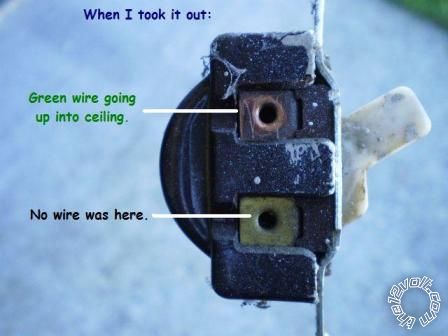
This would be an easy task IF my wires weren't installed 50-75 years ago in the stone age!!! Everyone says to look for black, white, and ground. Well, there are none of those. Here is what I have:
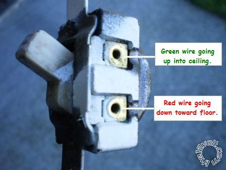
2 green wires (one on each side of old switch) going UP wall.
1 red wire to lower right side of switch going DOWN wall.
NO visible ground wire to box.
I do have a multimeter, and set AC voltage selector to 200 (only choices are 200 & 500, and when I set it to 500 it says High Voltage on display). So, I set it to 200. Touched ground lead to box and red lead to each wire and got these readings:
0 volts to lower red wire.
0 volts to upper left green wire.
1.2 volts to upper right green wire.
(I'm assuming that "1.2" is 120 volts.)
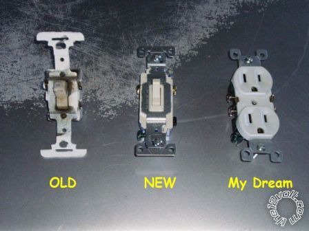
Okay, the reason I need this switch replaced instead of just hooking it up is because it's shorting out now and tripping my breaker. I went to Lowes and got a new 3-way switch since it looks like my idea of putting a plug there isn't going to work. But I also have a plug.
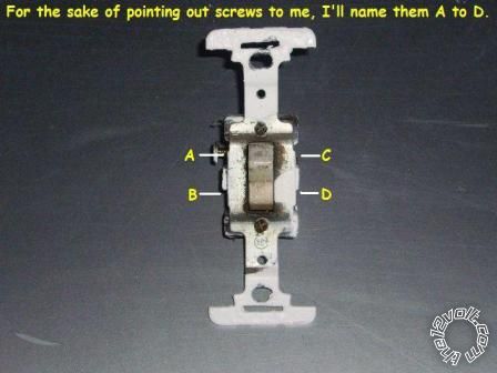
So, can someone tell me which wires are which, and which screws on NEW switch to attach them to? You can refer to the letters I put in the pictures or just upper/lower/left/right/etc.
If you know the correct way to wire the wall plug to the 3-way system, like just using 2 wires and capping off the 3rd, that would even be better.
Here are pictures for you to study. I need help. Right now I have no power to my overhead garage door until I replace the prehistoric switch with the new one (or the plug).

Replies:
Posted By: kenwood_nut
Date Posted: November 10, 2010 at 3:04 PM
Posted By: oldspark
Date Posted: November 10, 2010 at 5:20 PM
But as an alternative, I have some questions.
Is doing that sort of AC wiring illegal where you are? (It is here in Australia, but not in New Zealand. We both use 230V AC).
Do you use an earthed (grounded?) system?
Is it a MEN system (Main(s) Earth-Neutral; the neutral is bonded to the earth at a site's main switch board.
Does mains power (wall sockets) have to be earthed?
Do light circuits have to be be earthed?
(Hence...) Is it legal to take power from lighting circuits?
Do you have RCDs installed (Residual Current Devices)?
If so, for both lighting and power?
If so, separate RCDs for power and lighting?
Is the existing lighting on a light circuit or a power circuit?
If green is being used for L1 or L2 power (Active or Neutral), who the heck wired it and when?
What are the legalities of using a green wire for anything other than Earth?
What type and class of insulation and wiring currently exists? (Rubberised insulation that is breaking down?)
kenwood_nut wrote:Since the "box" is floating, why would you NOT expect to get any reading?
Touched ground lead to box and red lead to each wire....
Or - why did you expect to get a meaningful reading?
And yes, that reading was 1.2 Volts - it is NOT 120 Volts!)
Since it's a metal box, is it earthed?
Is it required to be earthed?
Are the wires run in conduits? If so, metal conduits, and earthed?
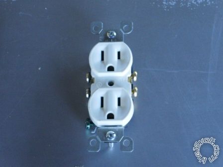
Looking at your "dream" socket in the orientation as shown above, which pin/terminal is required to be the hot or Active line (or L1 etc)?
What colors do you used for hot or Active conductors?
(Do you use the brown, blue & GREEN/ YELLOW system; or red, black, green; or some other convention?)
Unfortunately because AC systems and Regulations vary so greatly, and because your wiring is far from any Regulations I know of, I require the above before anything else.
However since this is probably a Regulated issue and has safety ramifications, I will probably chose not to provide direction other than the type of advice and warning in my first paragraph.
And this site may chose to lock this thread (but hopefully after your reply) if it is seen as a risk.... (Though there would be no direct legal issue if I were to advise a New Zealander, though indirect action is possible...)
I too get a kick from electricity.
Posted By: kenwood_nut
Date Posted: November 10, 2010 at 5:52 PM
That's funny... but true! No worries, I'm a little better than that.
Is doing that sort of AC wiring illegal where you are? (It is here in Australia, but not in New Zealand. We both use 230V AC).
Not that I've ever heard of. I'm just a homeowner (okay, renter, but don't tell anyone!) who needs to replace a wall switch. Perfectly legal here. I'm not doing any actual wiring or rewiring. Just replacing a bad switch.
So there ya go. I hope this answered some of your questions. Again, I believe this house was built in the 50's but it has been remodeled on the outside. But the wiring appears to be original. Even the furnace is from the 60's!
I still haven't found an answer to my question but DID find a site that showed what the OLD wire colors WERE and what they would be. Please tell me if these seem right....
Black, Red, or Blue (copper wire): hot
White (silver wire): Neutral
Green (or bare copper): Ground/Earth
Green with yellow stripe: Isolated ground
Thanks for at least replying to my post. You're the first one. I might have to just put the old, worn out switch back in so I can open my garage door with the button. If the breaker trips, I'll just reset it. It only trips when I flip that old, ancient, prehistoric switch.
Is it a MEN system (Main(s) Earth-Neutral; the neutral is bonded to the earth at a site's main switch board.
Do you use an grounded system?
It's certainly supposed to be, but I've found online that some are not grounded, or they are grounded inside the walls to each other (or something to that affect). But yes, they should all be grounded.I'm not really sure. If the wires were the correct colors of today's industry standards, I would know. I do NOT see a ground inside the junction box behind the switch. I know SOME are grounded from the switch to the box. Not this one.
Does mains power (wall sockets) have to be grounded? Do light circuits have to be be grounded? (Hence...) Is it legal to take power from lighting circuits?
Do you have RCDs installed (Residual Current Devices)?
If so, for both lighting and power?
Separate RCDs for power and lighting?
Is the existing lighting on a light circuit or a power circuit? If green is being used for L1 or L2 power (Active or Neutral), who the heck wired it and when?
What are the legalities of using a green wire for anything other than Earth? What type and class of insulation and wiring currently exists? (Rubberised insulation that is breaking down?)
Unknown on all of those questions. Again, I'm not rewiring anything so I haven't gotten into the wall electrics or done any inpections. As for WHEN it was done? Probably when the house was built back in the 50's or earlier. It's old wiring. But I've been here 2 years and never burned anything up or tripped a breaker no matter what I've plugged in.
Posted By: kenwood_nut
Date Posted: November 10, 2010 at 7:41 PM
2 green going UP the wall from the right side of switch.
1 red going DOWN the wall from the top left of the switch.
NO apparent ground (no wire to gox, no bare wire, etc)
Have new switch. So, which wire goes where on it?
Posted By: flobee4
Date Posted: November 10, 2010 at 8:37 PM
This is how i would attack this one if I was you. Its a lot of looking and alot of testing. But lets see what you got.
It sounds like the electrical box you are working at is not grounded nor has a neutral, so what you are trying to do there by adding and outlet is probably not possible...
If you want to replace the switch this is how I would test:
grab an extension cord that reaches from the back of garage outlet you mentioned in your post or an extension cord from any outlet and get it to the electrical box you are working at. make sure it is a 3 prong extension cord. Put your black probe in the ground hole on the extension cord, then with the circuit breaker on and the red and 2 greens hanging out of the box and seperated in a way not to short each other. touch the red probe to each wire individually. one has to be the "hot" wire or "feed" Once you find that wire, which i suspect is the red one, I would switch the other switch in the oppisite direction to see if you are in fact at the "master switch" if the red looses power and it jumps to another wire then you are at the "slave switch"
If you are at the master:
the constant 120volt wire goes to the black screw. again this wire stays constant at 120volts regardless of how the other switch is flipped. probably red, but test.
(2) other wires go to the brass screws - doesn't matter which goes where
If you are at the slave switch:
The 2 wires that toggle the 120volts during testing and flipping the other switch goto the 2 brass screws- again no important which of those 2 wires go where.
the 3rd wire that would have no power regardless of which way the other switch was flipped would goto the Black screw. This wire leaves the electrical box and goes to the light.
After testing and you are about to make your connections, makle sure you flip off the circuit breaker. When doing the testing, remember the wires will be live and the hot wire is the one that kills. especially when it crosses the heart.... example, left hand on ground and right hand on hot wire. path of electricity wants to goto ground, in that senario the fastest way is across the heart...
If you have any other questions, let me know. Work is pretty crazy right know, I might not be able to answer till late at night.
Frank
Posted By: oldspark
Date Posted: November 10, 2010 at 9:19 PM
You have been warned.
Of course there won't be any "ground" to the switch!
And I don't know how a switch can "short out" so that it trips a breaker. Are you able to explain that?
The reason no one has chimed in is probably because there is no guaranteed answer to your question, and people are wary of enticing you or others to their death.
I on the other hand don't mind the Darwin Awards, and I often get a chuckle watching people get shocked - whether it's though their teeth (water taps), opening a fridge door, or changing light bulbs. (It's not as if watching petrified kids that begin burn when train surfing - that stinks! Kids only stink after touching live AC fittings and switches if they haven't been found for a few days.)
Normally the 2-way switching switch uses three wires - the power in or out (Common switch pole) with the switchs' (SP)DT terminals interconnected (ie, 2 wires between the 2 switches).
And they should all be active (hot) connections (not neutral or ground!).
But there are other DANGEROUS (and illegal) ways of wiring them so be warned.
Make sure that you understand how to test for a live connection, and how to isolate the power and confirm that it is safe.
Assuming the circuit breaker or fuse is connected, you should have measured 120VAC (else a balanced 60VAC) on one of those 3 wires.
The fact that you didn't measure it suggest that you don't know how to.
TIP - use the back of your hand, not your tongue.
Posted By: kenwood_nut
Date Posted: November 10, 2010 at 9:25 PM
Posted By: kenwood_nut
Date Posted: November 10, 2010 at 9:28 PM
oldspark wrote:
Of course there won't be any "ground" to the switch!
Well this is a new one to me! I've had others tell me there MUST be a ground to the switch, and if there isn't, to make one.
Posted By: i am an idiot
Date Posted: November 10, 2010 at 9:39 PM
Posted By: oldspark
Date Posted: November 10, 2010 at 9:47 PM
Why would you have a ground to a switch? (Whether your ground is an Earth or Neutral does not matter.)
If those people telling you it "Must" have, then I'll assume that they are qualified people and therefore know that Regulations require that that be done.
But that is then becuase of Regulations - NOT because the switch needs a ground to function.
A shorting switch?
Do you mean that it is worn out so that is shorts the input to the output?
In other words, the switch is permanently on?
How does having a switch turned on trip the breaker?
A switch is a short circuit between 2 terminals. That is their intended design etc.
I'm not saying that a faulty switch cannot trip fuses & breakers, but it WILL NOT be because of an internal short.
And from what you said above, it is not possible for your switch to trip the breaker.
Hence I want to find out why your breaker is tripping.
It may be the switch, but it may be a problem elsewhere.
And you need to find out.
So have another go...
How does a faulty switch trip a circuit breaker?
An why does your non-existent ground wire(s) to the switch have to be there?
These are VERY SIMPLE domestic electrical questions.
Anyone that cannot answer them should be very wary of what tragedy may occur in the future.
And if you can answer them, you might understand why a 1.2V reading is 1.2V, and it might eve read zero volts even though are measuring a 120VAC or 240VAC wire.
Posted By: kenwood_nut
Date Posted: November 10, 2010 at 9:57 PM
But a few notes in regards to what you mentioned that I said...
I was told by a couple people that there shouldn't be a ground to the switch. But now they way you explain it, that all makes sense. So what you mean is I should ground the BODY of the switch and NOT the actual switch terminals? This is what I was thinking.
And about the breakers tripping: When I flip the old switch, it trips the breaker. Not sure why. But I'm "guessing" there is something bad inside it. If I flip the breaker, it won't re-trip. Not until I move that switch. I'm just guessing it has a short inside it. That's all I was trying to say.
Again, I do appreciate all the advice everyone has given me!!! I will use as much as I can to solve my problem. And like I said, ALL that I'm trying to do is keep power to my garage door opener. I don't care if there is a switch or plug there or nothing.
Posted By: flobee4
Date Posted: November 10, 2010 at 9:57 PM
A 3-way switch needs 3 wires to work and that's what you have. So, that means there is no ground wire in the box. it is possible that they grounded the box. But, I doubt that because you should have gotten 120 volt reading off one of those 3 wires when you placed the black test probe against the box and red probe against the 3 wires.
The neutral and the ground are connected to the same spot in the electric panel. While its ok to use either for testing for a hot lead with a meter, a ground and a nuetral cannot be interchanged. Thats why you are using the extension cord, to supply you with a testing point.
Posted By: kenwood_nut
Date Posted: November 10, 2010 at 9:59 PM
Posted By: i am an idiot
Date Posted: November 10, 2010 at 10:25 PM

Posted By: kenwood_nut
Date Posted: November 10, 2010 at 10:38 PM
Now I'm wondering if before I wrap things up, SHOULD I run a ground wire from the new switch's ground tab to the actual box? or not?
Thanks everyone! I really needed this help! Like I said, it's amazing how complicated home wiring is (with only 3 wires) as apposed to vehicle 12-volt systems (with a million different wires)!!!
Posted By: KPierson
Date Posted: November 10, 2010 at 10:45 PM
If you understand Bosch relays then you should understand 3 way switches. The actual switch acts as the coil of the relay, and the three terminals on the side of the switch represent 30, 87a, and 87. Back in college I used a DEI channel expander driving a 12vdc SPDT switch connected to a 3 way switch to be able to toggle the lights in my apartment from my car alarm remote.
-------------
Kevin Pierson
Posted By: oldspark
Date Posted: November 10, 2010 at 11:21 PM
kenwood_nut wrote:
I can't believe how different 12 volt vehicle wiring ... is from house wiring....
I stated this reply after that message. A few delays and a few other replies have crept in.
But FWIW.... (yes, a ramble...)
Well the switching is the same - you only need to switch the one pole.
Hence why you do not need other pole (ground).
But domestic AC usually mandates the switching of the ACTIVE conductor except where BOTH poles are switched (eg double-insulated).
Whereas that - and its logic - may not apply in car etc. A classic example that has recently resurfaced yet again - a "Battery Isolation Switch" that is used in competition etc vehicles to enable isolation of the battery in case of accident etc SHOULD be in the non-HOT circuit - ie, it should disconnect the battery's negative (ground) terminal from the chassis and loads etc. If the switch is next to the battery, it is no big deal. But when regulations require an isolation switch to be on the dash or console, or a rear corner of the vehicle, then isolating the +12V side is suicide! Some argue that in that case, it is safer with NO switch!
Now, do you ground the box etc?
My answer to that is "why create an additional risk?".
But your local regulations will state what is required. Refer to them.
(If your local regulations are a hazard, I empathise.... Been there, Done that!)
It sounds like you have the ever popular M.E.N system. (IE - power station outputs 2 AC lines - aka L1 & L2. They call L1 "Active" and bond L2 to (planet) Earth and call that "Neutral".
The Active L1 is distributed across the country.
Your Active goes via a fuse to your switchboard main switch and thence through fuses to different circuits (lights, power, kitchen, etc).
The Neutral also comes in to the main switch board (aka MSB) where is is bonded (joined) to an Earth Stake, otherwise Earths and Neutrals are kept completely separate in home wiring.
Earths are often literally just that - an Earthed connection meaning to planet Earth. Or yes, also called ground.
The Neutral however is the "return" for the Active circuit.
Power flows out the power station through the active, through the load, and back through the Neutral back to the power station.
That method means that fuses will operate given certain kinds of faults, and appliances should be at Earth potential so you don't get zapped. (Until lighting hits telephone lines etc... LOL!)
And the above is a simplification. In reality, 3 phases are sent from the power station, not "active and neutral". They are like three L1 lines or "actives" that are 120 degrees apart (aka 3-phase power). And there is no Neutral per se - "neutral" is a mid point between the 3 actives. (Neutral may be "reconstructed" at substations for distribution to consumers.)
But whereas the AC system used to be almost a floating or balanced system - ie, 2 pins and no Earth - the world is standardising on an Earthed distribution system - ie, 3 pins - Active (brown), Neutral (blue) and Earth (green or GREEN/ YELLOW).
Remember - if you touch the Brown, you will s.h.i.t yourself (poo your pants if that gets censored). That's how I remember. We used to have red = active and black = neutral and green = earth. They were easy to remember (red is hot and dangerous).
So back to your question. Do you ground the box?
Well, do you mean ground as in neutral, or ground as in earth?
Our regulations are quite clear - any mains (wall) powered device shall be in an earthed (metal) enclosure EXCEPT where it is a double insulated appliance (only 2 wires; special construction applies).
And earth means earth - the 3rd pin with its GREEN/ YELLOW wire to an "earthed ground stake" - NOT to the neutral pin or circuit.
So, refer to your regulations.
But I am certain that if you did that, you would be replacing your green wires. In most places in the world, that is a serious hazard - an accident waiting to happen.
As to your breaker tripping, as you should be able to appreciate, there is no way that the switch can short so as to cause MORE current to flow through the circuit (light) than the switch itself (ie, a clean contact switch).
So, is it an arc across the contacts that generates noise that trips the breaker?
Or is the breaker an RCD (aka earth or ground switch, aka "Safety(sic) Switch") that likewise is getting noise and tripping?
Or is the switch "leaking" through you or something and tripping the RCD?
Or is there an insulation breakdown so that when moved, there is leakage through <whatever> which is tripping the RCD?
The latter is often followed by fire.
The latter two are often followed by death, else maybe a cute shock if an RCD is installed AND is working properly (people rarely test them; hence they seize!).
I did write "a cute" shock because of my sick humor, but make that one word if RCDs are not fitted or if you place yourself across the neutral and active (without any earth leakage) as such shocks often are acute.
Forgive my narky attitude, but I no longer suffer Richard Craniums (aka Dik Heds).
And I do laugh - because seeing preventable tragedies is something I also try not to suffer. (Though it was funny seeing that guy on a train light up; fall stiff as aboard to the roof (making a hollow wooden sound as he did); then having spot-fires gradually ignite over his body. 1,500V DC - I'd rather 22,000V AC any day!)
But you may now understand some of my questions....
And you did give the answers I expected.
For some reason, people think switches must be earthed or neutralised. (Yet they know their ignition switch isn't, nor their 2-terminal switches.)
And for some reason, people think that short circuits blow things. [ EG - A common one - you keep blowing light bulbs; people often say "you must have a short". So how do you short a 12V supply into a 12V bulb? Else how does a short ACROSS a bulb blow it (assuming short intermittent shorts so that the fuse doesn't blow)? It's more likely a bad connection that makes & breaks - hence thermal shock etc. ]
Alas it doesn't take much thinking to realise the reality, it's just the we rarely do think...
Yet in retrospect it is all so obvious and easy....
Posted By: kenwood_nut
Date Posted: November 10, 2010 at 11:21 PM
My box IS metal. No ground. But my best friend said back in the 30's to 50's and stuff, they didn't use grounds in switches. Sure, things have changed, but that's part of why I'm having problems. Apparently wire colors changed too!
But I think I have it all figured out. A couple people have sent me very helpful tips and info that I have no doubt will help.
THANKS SO MUCH to everyone who replied. I really needed it, and was losing hope!
Posted By: i am an idiot
Date Posted: November 10, 2010 at 11:22 PM
Turn off the breaker that powers this circuit. Remove the switches one at a time, using an ohm meter, check to see which of the 2 terminals show a dead short on the meter. Now connect the 2 wires that came from those 2 terminals to each other. That switch is not out of the circuit. Insulate the remaining wire and turn the breaker back on and check to make sure all works. if so, kill the breaker again and do the same with the other switch.
Posted By: kenwood_nut
Date Posted: November 10, 2010 at 11:43 PM
So basically: this thread is dead. But I'm still alive thanks you you folks!