multimeter wizard?
Printed From: the12volt.comForum Name: Miscellaneous - Off Topic
Forum Discription: Topics that just don't fit anywhere else.
URL: https://www.the12volt.com/installbay/forum_posts.asp?tid=134228
Printed Date: April 01, 2026 at 2:54 AM
Topic: multimeter wizard?
Posted By: elkriverscott
Subject: multimeter wizard?
Date Posted: May 17, 2013 at 11:12 PM
This is an output sensor 2008 Sonata 3.3
It's 3 wire with 12 Volts going into it and one pin ground and one sensor. Will I damage it if I bench test by applying 12 volts, then ground and hook a meter to sensor output and ground? Is this a magnetic sensor and will a magnet produce anything to confirm? Test in AC?
If I had this back in the car would I jump the sensor wire and put it in drive? Meter on AC? (I put the front bumper against a wood pile and jack it up and use 4 jack stands.)
Getting way out there, can I meter test the output sensor pin on what appears to be the output cable of what I beleive to be a control module, bolted to the air cleaner. Can I fry anything just probing improperly?Thanks for viewing!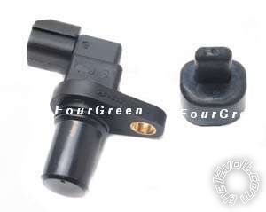
Replies:
Posted By: oldspark
Date Posted: May 18, 2013 at 12:30 AM
It should be fine. It should be a typical open-collector output, ie the output is to GND else it isn't, and damage should only occur if the +12V supply is not on its correct terminal, or you supply too high a current to its output.
And to test an OC output, use a high-ohmage resistance else diode-test range, or add a pull-up resistor (say 10k) if testing voltage.
In circuit, just measure the voltage. It should change toggle between ~0V and some +ve voltage eg, 3.3V, 5V. 12V etc.
And to test an OC output, use a high-ohmage resistance else diode-test range, or add a pull-up resistor (say 10k) if testing voltage.
In circuit, just measure the voltage. It should change toggle between ~0V and some +ve voltage eg, 3.3V, 5V. 12V etc.
Posted By: elkriverscott
Date Posted: May 18, 2013 at 1:25 PM
Thank you very much. I have a minimal knowledge of meters. Might I ask, if I am testing the output of a sensor in circuit do I set meter to read AC or DC?
About bench testing, do I hook up pwr and ground and then check output with red meter probe to signal wire and use common ground? I use resistance to check for output signal?
Thanks again, what scares me is my limited knowledge is often more than the mechanics. Go figure.
About bench testing, do I hook up pwr and ground and then check output with red meter probe to signal wire and use common ground? I use resistance to check for output signal?
Thanks again, what scares me is my limited knowledge is often more than the mechanics. Go figure.
Posted By: KPierson
Date Posted: May 18, 2013 at 6:30 PM
As it is a DC sensor use DC on your meter. You should not see an output under normal conditions and the output should switch on when you place a magnet near the sensor head.
The only way it would benefit you to measure it on AC is if the sensor is switching on and off too quickly to read as a DC voltage. The issue with setting the meter to AC is that it won't actually tell you anything valuable - just that there is something on the wire.
-------------
Kevin Pierson
The only way it would benefit you to measure it on AC is if the sensor is switching on and off too quickly to read as a DC voltage. The issue with setting the meter to AC is that it won't actually tell you anything valuable - just that there is something on the wire.
-------------
Kevin Pierson
Posted By: elkriverscott
Date Posted: May 18, 2013 at 6:51 PM
Thank you so much. You are now too cool for the room.
Posted By: oldspark
Date Posted: May 18, 2013 at 7:10 PM
You already know as much as about mechanics - but maybe I'll qualify that later...
As to MMs - hereby referred to as DMMs since most these days are digital (Multi-Meters) that contain combinations of volt meters, resistance meters, current aka ammeters, frequency, capacitance, inductance, temperature... and testers for diode, transistors, continuity...
The first rule is never use the resistance range on a powered circuit.
Another first rule is never an ammeter (current range) across a voltage source - it needs to be inserted inline aka "in series".
And of course the first rule - make sure the meter and its probes are appropriately SAFETY rated.
The second rule - well, I can't think of any as such. The first rules (LOL) above are to prevent meter damage, and damage to circuits or YOU.
After that comes the understanding of how to use them - eg, maybe start off on a high range for non auto-ranging meters, and stay away from hazardous voltages unless you know what you are doing and have properly rated equipment (Cat II & III etc).
You should be able to find web sources that will teach or show you how to use a DMM. (Hey man, I just poured coffee beans into my espresso machine instead of the grinder, so I'll leave those tricky search & google things to you.)
But I'll short-circuit some of those lessons with a few tips... (... oh my puns...)
Never short-circuit circuits with the tips if a probe, nor the ammeter range.
That includes testing ACROSS batteries for current. Even a small button of flattish AAA will probably blow a DMM's internal fuse (typically 250mA).
If ever using a 10A or similar Amp range that requires reconnecting the DMM probes, return the probe(s) to their usual volts terminals when finished. That prevents the next test being a short across whatever - maybe a 12V battery - even though the "meter" is set to Volts.
Let's just say the above is a rule that I RE-discovered last week... again! (I set the dial to 20V to measure my HU's supply voltage not realising the + probe was still on the 10A terminal!)
Maybe I should explain (as I once did to a 3rd year electr* engineering student)...
An ammeter is LOW impedance (resistance). It's like a short circuit (aka crowbar or metal ladder).
Hence like a wire it can be connected IN LINE with a battery or voltage source etc, but NOT ACROSS the battery terminals or voltage source.
Voltmeters are the opposite - high resistance (impedance).
Hence you can connect across battery and voltage terminals and NOT cause high current flows as short-circuits do.
(And in series, it will stop current flow, and measure the "open circuit voltage" of that part of the circuit.)
The above seem complex but become easy with experience and understanding.
It's usually 2 issues - hi or lo meter resistance, and powered or passive/unpowered testing.
Measuring 12V automotive stuff usually does not need much more than a basic understanding. Generally DMM impedances are NOT similar to vehicle impedances and thus do not have to be considered.
Now to YOUR questions...
Test lead polarity usually doesn't matter for DMMs.
If connected backwards for DC, the meter will show a -ve voltage eg -12.6V instead of 12.6V.
For analogs it may matter. The -ve DC voltage will push the needle down past 0V, out the LHS of the meter and chop your hand off. Ok, not quite. Nor should it damage the "meter" itself (needle etc) and damage to other components is rare.
AC or DC range?. ROT (rule of thumb) - DC range for DC vehicles.
But "DC sensors" and circuit can produce AC outputs.
And it depends what you want to measure, eg average DC value or average ripple voltage?
I'll often reverse the probe polarity and even try both AC & DC ranges.
The above can depend on how the meter measures - ie, thru diodes, or chip calculations.
But most AC meters will measure "ripple" even if it's DC. [Peoples definition of AC & DC vary. Some consider a noisy or ripply +12V to be DC while others (like me) consider it AC with a DC offset. In simple terms, DC has no frequency - it is 0Hz whereas AC has a frequency - and hence we can (more simply) explain all the circuits we build.]
Alas the fun discussions and fun - or painful - trails and errors in this game. We prefer the search & learn or discuss over the painful errors.
But it can be colorful. I still see authors and experts argue or question whether electricity is the movement of electrons or +ve charges when in fact it is both yet neither.
Anyhow, I've probably totally bamboozled you or scared you off with my usual bulk. (I might even have stirred some others....)
And you find others or sites that will get the above across better and simpler.
And now my coffee is bout to bubble...
But one extra reinforcement and one tip...
ONLY voltage ranges across powered circuits or components (NEVER resistance/Ohms scales, and rarely current ranges).
NEVER test a vehicle oxygen sensor using a resistance range - even a 1uA injection can kill the sensor. Testing their voltage in circuit may be ok.
Now, about those mechanics....