Making Sense Of Wiring In A Home Made Childs Toy Car
Printed From: the12volt.com
Forum Name: Miscellaneous - Off Topic
Forum Discription: Topics that just don't fit anywhere else.
URL: https://www.the12volt.com/installbay/forum_posts.asp?tid=146827
Printed Date: May 23, 2026 at 9:39 PM
Topic: Making Sense Of Wiring In A Home Made Childs Toy Car
Posted By: wamphray
Subject: Making Sense Of Wiring In A Home Made Childs Toy Car
Date Posted: April 26, 2021 at 7:53 AM
Can anyone help me make sense of the wiring on a childs toy car, made out of an elderly electric wheelchair thirty years ago, and now being refurbed. The original motor has gone and I cant work out where the wires should go when trying to fit in a new motor.
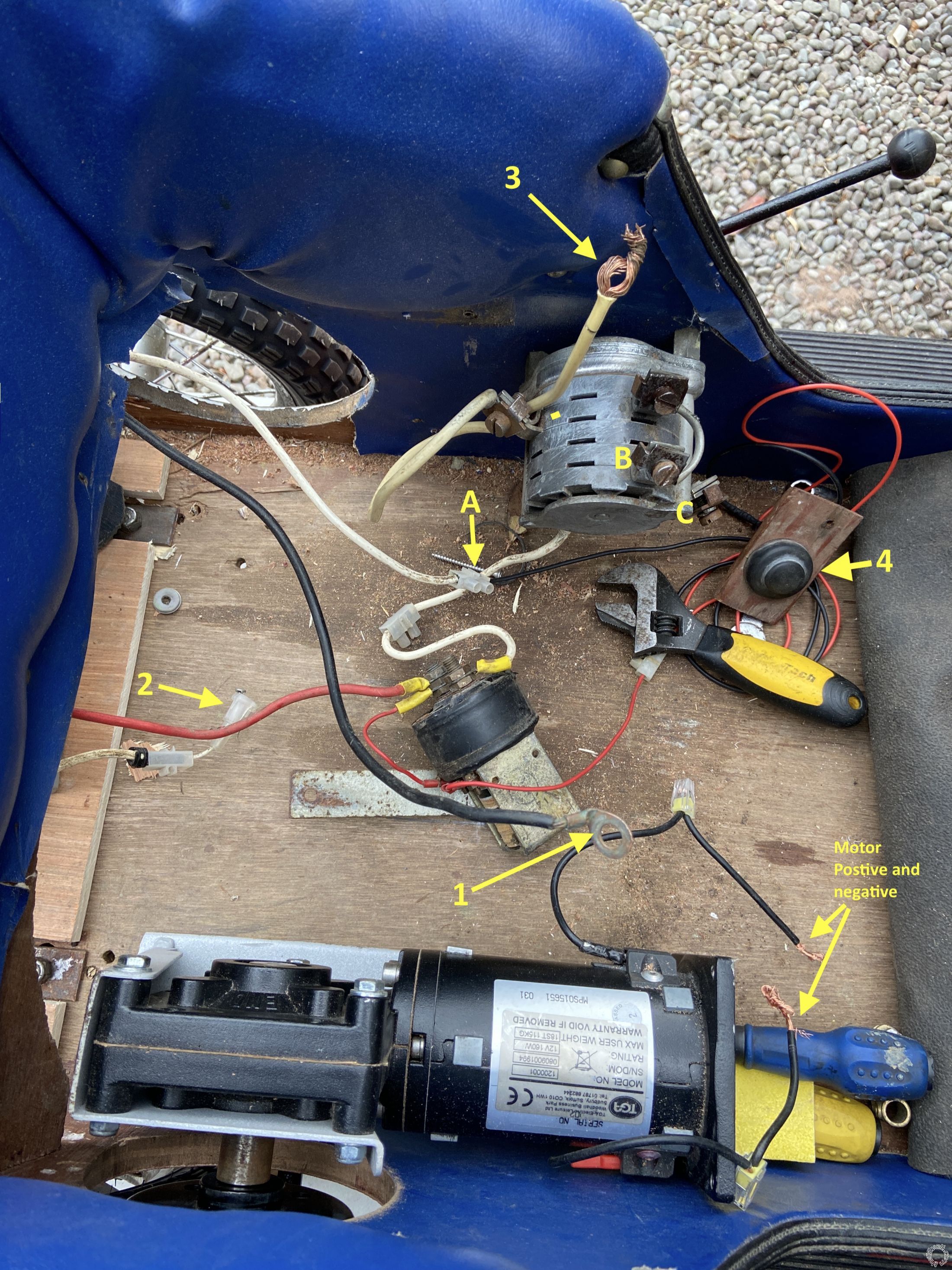
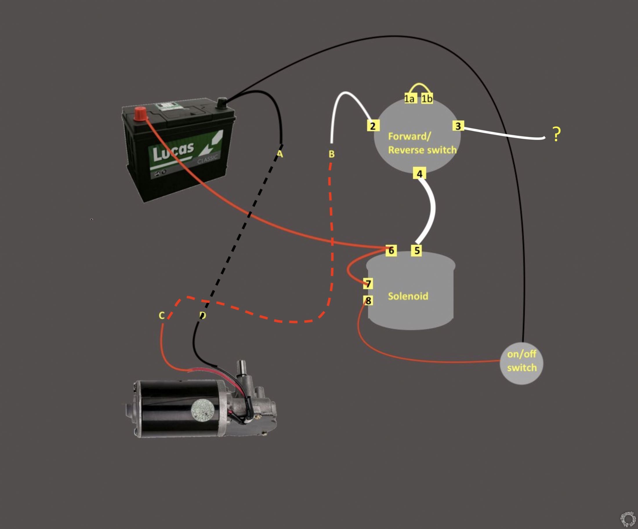
The attached picture shows the set up. The black handle at the top of the picture made the car go forward or back. It used to drive the wheel seen at the top left but the new motor is mounted to drive the opposite wheel. I havent yet blanked off the hole left by the removal of the old motor.
No 4 is the button which makes the thing go. It sat on the floor and was pressed with the foot. One wire goes from it to the side of the solenoid. The other goes - through a Terminal Block and white wire (marked A) to the negative terminal on the battery. At the moment, when power is applied, the solenoid makes a clunk noise.
Wire No 1 goes straight back to the negative terminal on the battery.
Wire No 2 (which must once have gone to an in-line fuse) goes to the positive terminal on the battery.
The terminal at B was loose and I dont know if anything was attached to it (or should be).
The terminal at C seems to have had something attached to it.
I am enthusiastic but not very good with electrics. If anyone can tell me how to wire it up to make it go forward or backwards it make my granddaughter very happy.
Thanks in advance for any help.
John
Replies:
Posted By: wamphray
Date Posted: April 26, 2021 at 7:58 AM
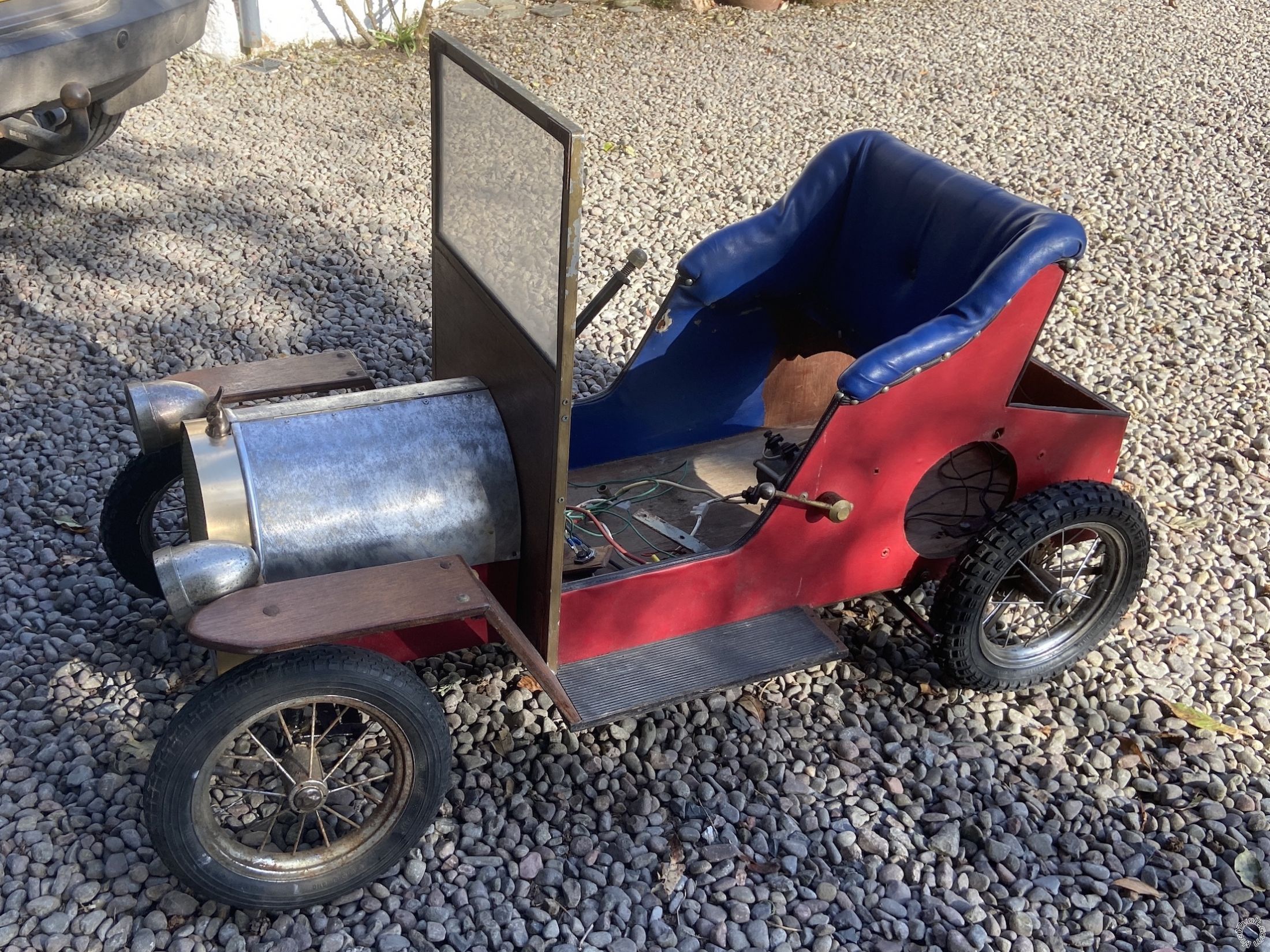
And here's a picture of what the whole car looks like at the moment ...
Posted By: i am an idiot
Date Posted: April 26, 2021 at 2:04 PM
I have a few questions.
Do you have a multimeter?
The 2 terminals on top of the switch, is that a jumper connecting them together? Was that there initially?
How many connections on the forward/reverse switch?
Does that switch also control speed?
Posted By: i am an idiot
Date Posted: April 26, 2021 at 2:13 PM
From what I am thinking, do not attempt any of this till we verify with a meter.
The white wire and the terminal on left of forward/reverse switch is power input.
Terminal C is ground input to switch. I am thinking that Ring 1 was connected there.
The 2 terminals on top of switch go to the motor.
It will be very simple to confirm these connections with an ohm meter.
Posted By: i am an idiot
Date Posted: April 26, 2021 at 2:18 PM
Does the red wire go to the positive terminal of the battery?
The white wire with the homemade ring terminal should go to the other terminal on top of the solenoid.
Posted By: wamphray
Date Posted: April 27, 2021 at 12:02 PM
Thanks for the replies.
Yes. I have a multimeter although I don't really know how to use it. I treat it like a test bulb.
Yes .. There's a jumper at the top of the forward/reverse switch. It has always been there, although one side was not tightened down, as if something had been removed from it.
There are five connections on the Forward Reverse switch (including the two jumpers). One is not visible in my first photograph.
There is no speed control - just a button on the floor which is effectively and on/off switch. As long as it's pressed, the car moves.
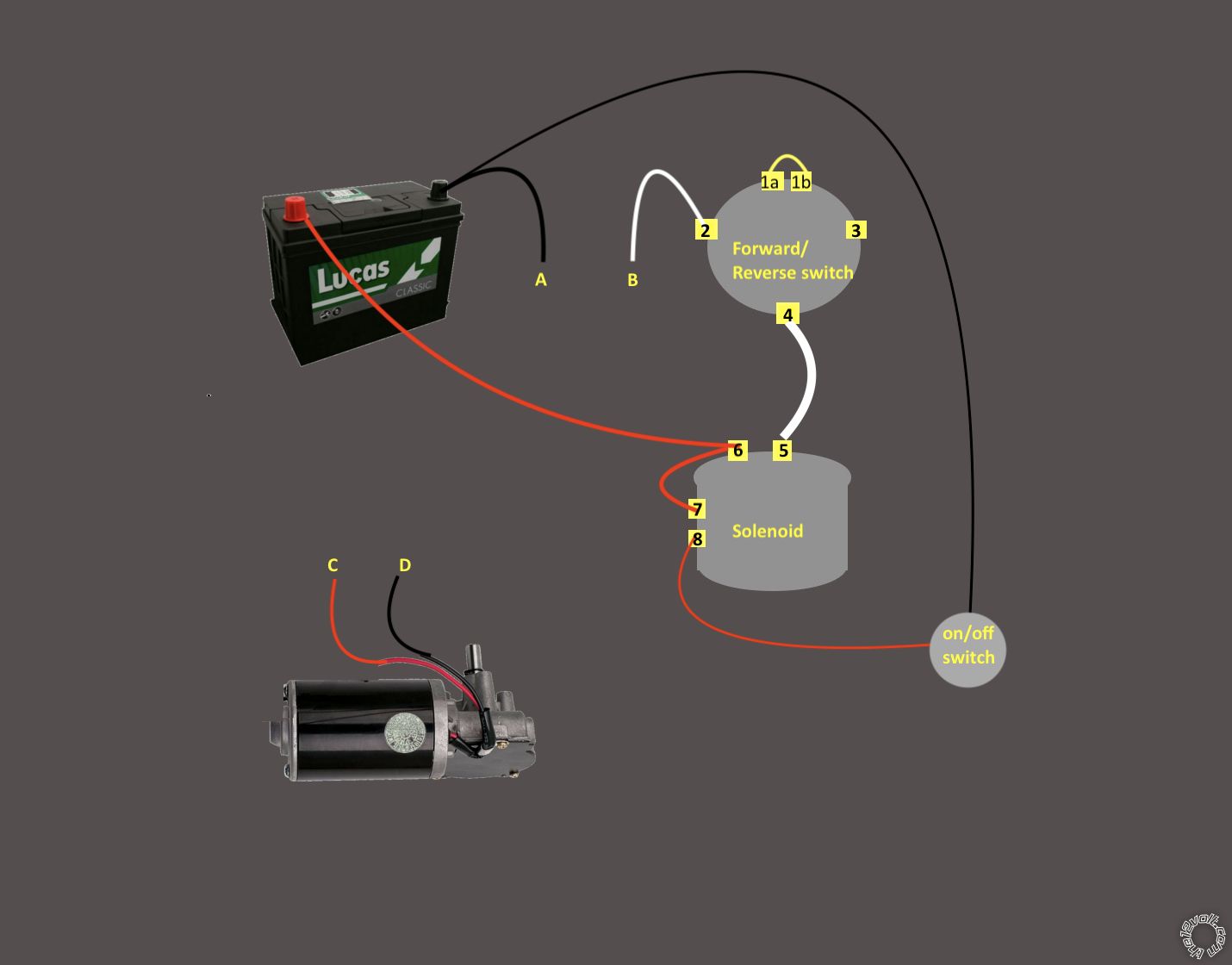
I've drawn up a wiring diagram of the wires as they are currently connected - I'm fairly certain they're connected as they were when the car worked with its previous motor.
I suppose my question is where do wires A,B,C & D go?
Posted By: i am an idiot
Date Posted: April 27, 2021 at 6:56 PM
Remove jumper from 1a to 1b.
Set meter to the ohm setting. If it is not an auto ranging meter set it to 200 ohms.
Set forward / reverse switch to forward.
One meter lead on 1a, other meter lead to each other terminal and post the readings
To 1b
to 2
to 3
to 4
Then one lead to 1b and the other to each other and post those readings.
To 1a
to 2
to 3
to 4
one lead to 2 and the other lead to each other and post
To 1a
to 1b
to 3
to 4
One lead to 3 and other lead to each other
To 1a
to 1b
to 2
to 4
Switch to reverse and do the same.
Posted By: wamphray
Date Posted: April 28, 2021 at 5:11 AM
Thanks for writing out such clear instructions. Everything worked better when I changed the battery in the multimeter!
The forward/reverse switch has four positions (and rotates between them endlessly in either direction).
I followed your plan in each of the four positions. There were no readings in Positions 1 and 3.
In Position 2, there was a reading (of 1.2) when the meter was connected across terminals 1b and 2
In Position 4, there was a reading (of 1.4) when the meter was connected across terminals 1a and 3
Does that point the way?
Posted By: wamphray
Date Posted: April 28, 2021 at 5:15 AM
By the way: I was talking nonsense when I said that one side of the jumper appeared to have been untightened (as if something had once been connected to it). I was getting my terminals mixed up. Both jumpers were tight (and the exposed end of the threads were uniformly corroded). I don't think there had ever been anything else connected to the jumper.
Posted By: i am an idiot
Date Posted: April 28, 2021 at 7:56 PM
I do not have enough data. Did you perform all 16 of the tests?
Posted By: wamphray
Date Posted: April 29, 2021 at 6:25 AM
I did but not well enough, I guess. So I cleaned all the terminals as thoroughly as I could, and ran all 16 of the tests again. The only readings I found were as follows:
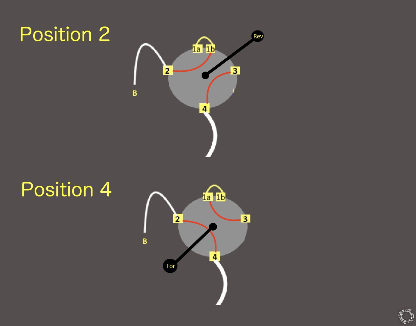
In Lever position 2: There was a reading between terminals 1b and 2
and between terminals 3 and 4
In Lever position 4: There was a reading between terminals 1a and 3
and between terminals 2 and 4
No other terminals showed any connections in any of the four lever positions.
To help me understand it, I did another wee diagram which I'll post in case it helps. The lever positions show with the forward/reverse positions as I remember them when the car worked.
Thanks again for your help. I really appreciate it.
Posted By: i am an idiot
Date Posted: April 29, 2021 at 11:54 AM
That is enough data. I will look at it tonight.
Posted By: i am an idiot
Date Posted: April 29, 2021 at 8:11 PM
2 to one motor wire.
3 to the other motor
Power to 1a and 1b that explains the jumper.
Ground to 4.
If it goes backwards when in forward and goes forward when in reverse, simply reverse the 2 motor wires.
Posted By: wamphray
Date Posted: April 30, 2021 at 12:41 PM
Thank you for your help. I do appreciate it.
T4 is already occupied by a wire from the solenoid (which is live when the on/off switch is activated).
I ran wires as per the diagram below, with the For/Rev switch in Position 2 and it drove the motor forward.
When I moved the lever to Position 4, and connected T3 to the motor (wire c) it also drove the motor forward.:errr:
Posted By: i am an idiot
Date Posted: April 30, 2021 at 8:13 PM
4 to power
1a and 1b both get ground.
2 to one wire of the motor
3 to the other wire of the motor.
Posted By: wamphray
Date Posted: May 02, 2021 at 12:27 PM
Bingo! - as we (used to) say in the UK. It's works as it did back in the old days.
If you lived near here,I'd buy you a pint .. best I can do is send you a picture of one.
Thank you so much for your help.

Posted By: wamphray
Date Posted: August 01, 2021 at 10:46 AM
Okay - here's the thing: The motor works and the car drives along pretty nicely. The only thing is that the motor gets very hot. The battery loses punch after about half an hour (which is fine as it's just a toy for the grandkids) but I suspect it would last longer in a wheelchair. Do I need something in the circuit to stop the motor heating up or do I just live with it?

Posted By: i am an idiot
Date Posted: August 01, 2021 at 2:59 PM
If you are using a wheelchair motor, different gear reduction may be in order. How fast does this thing go? If you raise the wheels off the ground and run the motor without a load on it, does it still get hot?
Posted By: wamphray
Date Posted: August 03, 2021 at 11:14 AM
Thanks for the reply.
It goes at walking pace - say 3.5 mph? When I first got it working, it was too fast, and the chain kept coming off. IO increased the size of the sprocket on the motor to slow it down a bit, and got the alignment right and it worked fine. It was only when I was putting it away that I noticed the heat in the motor casing.
I'll put it on blocks and run it for a while and report back.
John
Posted By: i am an idiot
Date Posted: August 03, 2021 at 6:29 PM
Increasing the size of the sprocket on the motor should have made it go faster. If that did slow it down it is putting that motor in a bind. A smaller drive sprocket should slow it down and make it much easier on the motor.
|