Hello, I have used relays before for simple applications. However, what I am trying to do now is a little beyond me. Basically, I wanted to see if there was a latching relay available to do the following or if I could contruct sometine to do the following using a series of relays. Any help would be appreciated.
Situation: Two different sets of triggers both with negative pulsed output. I need one pulsed output to turn on a relay and send +12 volt (or ground) and the other pulsed output to turn off the relay. There may be multiple pulsed outputs from the on or the off trigger so I can't use a simple latching relay with one negative trigger input like the one in the help section. The system needs to have the ability to see multiple pulses from the first trigger (on) and keep the system on or see potential mutiple pulses from the second trigger and keep the system off.
Example:
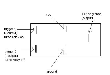
Check out this relay diagram. I've been trying to make my own diagram out of that by adding in a relay - unfortunately my MS Paint skills are mediocre.
What you would do is(assuming you want a 12v+ output) connect your turn-ON trigger to the (-) input on the left relay. That will keep it on regardless of how many pulses it sees on the (-) wire, since the 2nd relay is latched with the first pulse.
Your turn-OFF trigger would go to a 3rd relay, which would interrupt the ground to pin 86 of relay 2. Relay 3 would be wired as follows:
85: (-) turn-OFF trigger
86: constant 12v+ fused
87: no conn.
87a: pin 86 of relay 2
30: chassis ground
This relay obviously only activates with the turn-OFF pulse.
In addition, I'm not sure where your turn-on and turn-off are coming from. If you just have manual switches, the diodes shouldn't be necessary.
If you are using alarm outputs for control, diodes should be used on relays 1 and 3 to avoid voltage spikes - the striped side of the diode should go toward whatever pin (85 or 86) has 12V+ constant.
Assuming you wanted a (-) switched output, the following would be changed:
Pin 30 on relays 1,2 would be chassis ground
Pin 30 on relay 3 would be 12v+ fused.
-------------
C Renner's Auto Electronix
My service is cheap, quick, and good - pick any two
That looks like it would work. I looked at that page before but never thought about adding a third relay to that example. Thanks for the help!

hi,
how much current are you looking to switch. they do make dual coil latching relays in rather small dimensions that will switch as much as five amps of current. and yes they will take multiple inputs to the same coil without ill effect. not as fun as to build yourself but probably less expensive in the long run.
mark
-------------
John DeRosa (Hotwaterwizard)
Stockton California
When in doubt, try it out !
-------------
John DeRosa (Hotwaterwizard)
Stockton California
When in doubt, try it out !