relay, need a reverse circuit.
Printed From: the12volt.com
Forum Name: Relays
Forum Discription: Relay Diagrams, SPDT Relays, SPST Relays, DPDT Relays, Latching Relays, etc.
URL: https://www.the12volt.com/installbay/forum_posts.asp?tid=103500
Printed Date: January 13, 2026 at 11:39 PM
Topic: relay, need a reverse circuit.
Posted By: skeeler
Subject: relay, need a reverse circuit.
Date Posted: March 29, 2008 at 3:56 PM
Hi guys! Hopefully you guys can help me. I am at a loss.
I have a wakeboard boat with a water ballast system in it to increase the wake size. The ballast system is controlled by three reversible pumps. These are jabsco pumps that are reversible. So when connecting + to +, and - to -, the pump brings water in, when hooked up in the reverse order, it takes water out. Currently they do this, but the factory relay network in place now has timers that only allow the system to run so long. I need it to run longer, and would like to eliminate this circuit with a new one.
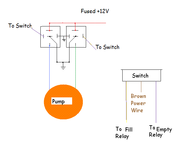
So heres where I need your help. I need a relay circuit to accomplish this task. The wires running from the switch to control box are as follows;
Green - LED
Yellow - Fill
Brown - Power
White - Empty
The switch wiring cannot be altered due to the way it integrates into the display gauges. Thanks in advance guys, I appreciate it very much!!!!!
Replies:
Posted By: skeeler
Date Posted: March 29, 2008 at 4:00 PM
I forgot to mention. The switch that is used is a on/off/on toggle switch with an led in the toggle. Thanks again!
Posted By: i am an idiot
Date Posted: March 29, 2008 at 5:25 PM
Is there some sort of limit switch on the ballast tanks? If the ballast tank overflows where does that woter go? I am not going to help you sink your boat. If he has limit switches and we are sure he is not going to sink his boat. What I had in mind was a reversal rest at ground. If nobody helps you with this, I will be back Monday evening.
Posted By: skeeler
Date Posted: March 29, 2008 at 6:07 PM
Thanks for the concern, but rest assured the boat won't sink.
Let me clarify. The boat is equipped with three hard ballast tanks built into the hull with three separate pumps. Each tank has two plumbed hoses to them. A fill, and a vent/overflow hose. When the tank is full, the water comes out the side of the boat. In order for this water to enter the boat causing a potential sinking a few things would have to take place. One of the hoses would have to some how come off. If this would be the case, the boat already is equipped with three automatic bilge pumps that turn on automatically when water is present.
The reason the manufacture went with the timed network was because people were forgetting to turn the pumps off and burning them up causing warranty issues. They had the pumps wired this way for the past 12 years, but have recently change them in '07.
I would love to go back to the old way.
Posted By: i am an idiot
Date Posted: March 29, 2008 at 6:22 PM

This should do the trick. As long as the time circuit is not in the power that supplies the switch. The yellow and white wires did not show up so good, but the switch in the picture is the existing switch in the boat. You will have to build the relays and attach the yellow and white wires from the existing switch to the relays.
Posted By: skeeler
Date Posted: March 29, 2008 at 6:35 PM
Thanks! I will give it a try and let you know how it works. Thanks again.
Shawn
Posted By: skeeler
Date Posted: March 29, 2008 at 7:20 PM
Well, I just tried that and no dice. Didn't turn on the pumps at all. Any other thoughts? Does that "power" wire from the switch need to be in the mix?
Posted By: i am an idiot
Date Posted: March 29, 2008 at 8:06 PM
The switch is the actual switch already on your boat. Are you sure that the brown wire going to the switch is actually power? If the brown wire is not a positive wire then this will not work. I am on the way out the door I will be back Monday evening.
|
