first post, dual source relay control?
Printed From: the12volt.com
Forum Name: Relays
Forum Discription: Relay Diagrams, SPDT Relays, SPST Relays, DPDT Relays, Latching Relays, etc.
URL: https://www.the12volt.com/installbay/forum_posts.asp?tid=104875
Printed Date: May 03, 2026 at 11:10 AM
Topic: first post, dual source relay control?
Posted By: wyatt earp
Subject: first post, dual source relay control?
Date Posted: May 20, 2008 at 8:31 PM
Ok, guys, I tried a search and couldn't find what I was looking for so here goes: What I am trying to do is this: With a manual transmission (NV5600, 6 speed) take the signal from the reverse switch and turn on both the OEM reverse lamps as well as the auxillary trailer lamps - ok well that's the easy part. The trouble is this, I also want to take that relay or relay's and have a manual override switch where by without the vehicle in gear to have the lamps turn on with a manual override. Sounds simple enough but to complicate things the override switch I have has a bulb in it to indicate when it is in operation. I can build a set up that powers each option but not one that does both. If I wire both the source from the switch and the transmission into the same point on the relay (86) the lamp on the switch will come on if the transmission tigger was used because the feed backs up through the switch and goes to ground across the bulb. My scanner doesn't work with vista so I may have a little trouble drawing what I've tried. I am thinking that the use of a normally closed and a normally open relay may do the trick. The trouble is I don't know how to tell the difference between the SPST items at the supply house. My knowledge of 12V electrics is medium at best. Your assistance would be greatly appreciated. PS: I really like pictures to help me "figure" things out. If they are on this forum please send me a link to the correct one. Thanks for all the help. Cheers. ------------- Wyatt Earp
Just another Diesel Performance Nut
Replies:
Posted By: wyatt earp
Date Posted: May 21, 2008 at 9:18 PM
Ok, well since I didn't get any replies I started thinking and looking on this site and others in greater detail and I'm wondering if anyone can tell me if I'm on to something with the following idea: Relay 1 (the transmission switch) would be a SPDT 86 - from transmission 30 - from battery 87a - N/C 87 - N/O power to lights 85 - ground Relay 2 would be for the cab switch and is a SPST 86 - from switch 30 - from N/C (87a) of relay 1 87 - N/O power to lights 85 - ground My idea goes like this - generally the cab switch is off (N/O) and the lights are only generally triggered by the transmission switch. If the 86 on relay 1 is NOT energized the power from 30 (#1) goes through 87a (#1) and heads to 30 (#2) and stops and is available for user input from cab switch. If 86 (#1) is energized (Closed) then the power 30 (#1) runs through 87 (#1) and powers the lamps. If the cab switch (relay 2) is used when the truck is in reverse it wouldn't matter because it is already energized but should the transmission go back to neutral (open switch) then the power would be as explained above and now go from 30 (#2) and travel through 87 (#2) and power the lamps. So, is that the right idea? Please let me know if I'm on to something as this is all a bit too confusing for me. ------------- Wyatt Earp
Just another Diesel Performance Nut
Posted By: dustysnakes
Date Posted: May 21, 2008 at 10:24 PM
ok lets try to simplify this a bit from what im gathering you essentially have two input sources or triggers rather that you want to work independantly of each other?
-------------
keep it greasy
Posted By: wyatt earp
Date Posted: May 22, 2008 at 12:21 AM
Yes, correct.
-------------
Wyatt Earp
Just another Diesel Performance Nut
Posted By: dustysnakes
Date Posted: May 22, 2008 at 12:36 AM
ok then why do you need to come from the tranny relay to the #2 relay for power you look right besides that but i could just be missing somthing too. the outputs shouldnt feed back through the relays as the circuits will be broken when the triggers arnt engaged
-------------
keep it greasy
Posted By: wyatt earp
Date Posted: May 22, 2008 at 9:10 AM
But unless I can find a DPST relay which I don't think exist, I don't want the bulb in the switch to go to ground which is what was happening. The bulb should only be lit when the switch is in use, not back fed some thing else. If I'm wrong well then so be it. It is just I had a single relay set up and it didn't work so then I put 2 in parallel and that had problems now I would like to try this but I don't want to really start hacking and slashing so to speak until someone agrees or points out flaws. Thanks ------------- Wyatt Earp
Just another Diesel Performance Nut
Posted By: KPierson
Date Posted: May 22, 2008 at 1:02 PM
Honestly, I didn't read the entire thing as there are lots of numbers and descriptions and my ADD prevents me from comprehending them all, but I would assume you could diode isolate the output of the switch so that it will prevent the back feed from the reverse signal from turning the light on.
-------------
Kevin Pierson
Posted By: wyatt earp
Date Posted: May 22, 2008 at 4:04 PM
Kevin, As I said I'm not very up on this stuff - esp. diodes - how do you do that? ------------- Wyatt Earp
Just another Diesel Performance Nut
Posted By: KPierson
Date Posted: May 22, 2008 at 4:55 PM
A diode is used as an isolation device - it only allows voltage to flow in one direction. You can pick up two diodes (1A would be fine) at Radioshack for $0.99. Diodes are polarized, so you MUST put them in the right direction. Basically, what you would do is similar to what you have above: Relay 1 (the transmission switch) would be a SPDT 86 - from transmission THROUGH DIODE - STRIPE SIDE CLOSER TO RELAY 30 - from battery 87a - N/C 87 - N/O power to lights 85 - ground Only the current requied to energize the relay will go through the diode, so you are looking at ~150mA (that is where the 1A rating comes from - standard value much higher then what is needed). Now, to install the switch, you will want to attach the input side of the switch (switches with lights have dedicated in and out pins) to the battery (make sure this feed is fused appropriately). Connect the output side of the switch to the non striped side of the 2nd diode (yes, you will use them both). Connect the striped side of the 2nd diode to the striped side of the first diode (or pin 86 of relay 1). The diodes will prevent the voltage from the tranny backfeeding in to your switch. It will also prevent the voltage from your switch from backfeeding to the tranny switch (most likely not an issue, but on some cars the ECU may monitor the reverse signal). I would draw a quick picture but my laptop is broke right now and that is where all my pretty little templates are! ------------- Kevin Pierson
Posted By: 98neonr/t
Date Posted: May 22, 2008 at 6:26 PM
you could use the diode but a little simpler idea would be to use an LED witch basically is a diode and will do the same tihig but it will be easier to understand because most have a+ and - on the wires wich makes it easier
-------------
i kant spel
Posted By: KPierson
Date Posted: May 22, 2008 at 6:47 PM
You could do that, but stripes arn't that hard to figure out! Plus, you would need to find an LED that has a current capacity of at least 150mA. That may not be easy to do, especially at Radioshack. If you try to add a current limiting resistor (or a 12vdc LED) you won't have enough current left over to energize the relay. Just get the diodes, its the "right" way to do it and you don't have to worry about blowing things up by running too much current to them! ------------- Kevin Pierson
Posted By: wyatt earp
Date Posted: May 22, 2008 at 8:55 PM
Thanks guys. I don't want to split hairs here. I'm just trying to learn how to do it beyond just plugging in a 85 and a 30 (basic stuff). I need to find a way to draw and post here on line without dealing with my idiot scanner. Any ideas? ------------- Wyatt Earp
Just another Diesel Performance Nut
Posted By: astrosurfer
Date Posted: May 23, 2008 at 9:26 PM
this can easily be done with a 5 pin relay...
closed normally would be your transmission circuit + or -.
closed energised should be your manual override circuit.
basically you would be just changing the feed to the lights.
wire the switching terminals to 12V and imagine it like train tracks.
i don't see the need for diodes to make this work.
just my $0.02
Posted By: KPierson
Date Posted: May 24, 2008 at 2:27 AM
A $4 dollar relay or $0.99 in diodes - they both will work, but the diodes are a bit more simplistic, have a lower cost, and a lower failure rate. Diodes are isolation devices and relays can be used as isolation devices. If it were my car i would go diodes! ------------- Kevin Pierson
Posted By: wyatt earp
Date Posted: May 24, 2008 at 11:19 AM
So, what you are saying is that if I turn the relay polarity around (the 87 and 87a would be inputs not outputs) that this should work with a normal 5 pin? Sounds simple enough. I didn't know you could do that to be honest. Thanks ------------- Wyatt Earp
Just another Diesel Performance Nut
Posted By: i am an idiot
Date Posted: July 27, 2008 at 9:54 AM
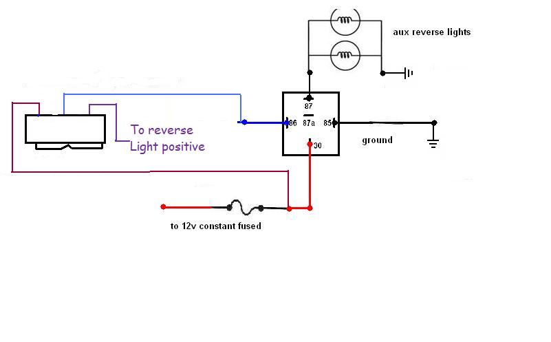
The switch on the left of the picture is an On-Off-On Single Pole Double Throw switch.
|