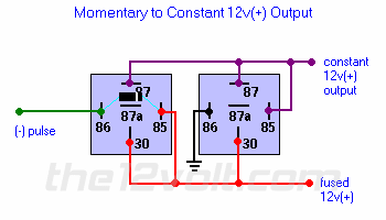
Can someone explain to me how the Momentary to Constant 2 relay setup works? The diagram is in the relay section of this site. I am very familiar with spdt relays and I am a MECP certified Installer however this setup is confusing me. I dont see how one of the relays is going to stay latched once the - pulse from the alarm or whatever is removed? Is this a special type of relay that becomes latched with just a single pulse? If so whats the need for two relays? Also I see there showing a diode across the coil of one of the relays I had always thought all relays had a diode across the coil. Can someone clear this up for me.
Thanks,
Anthony
not all relays have a diode across the coil....i know this coz i have one. as for the relay setup....if you look at it right it's a power loop back across the relay from the pulse trigger. the pulse closes to poles 87+30 and the coil stays energized from that voltage too. Take ground or live away...bye bye coil energy...back to normal. i hope this explains it for you.
I'm sorry I'm very familiar with regular SPDT relays but this is confusing to me. What is the purpose of the diode in this setup? You said
"it's a power loop back across the relay from the pulse trigger.
the pulse closes to poles 87+30 and the coil stays energized from that voltage too"
I understand what happens when the coil is energized but as soon as the - pulse is taken away how do you figure the coil is going to stay energized? The voltage going through 30 to 87 should have no effect on the coil.

The relay on the left energizes only when the pulse is coming in, and when it does, it connects the 12V input from the bottom (terminal 30) to the top (terminal 87).
The 12V goes to the coil of the relay on the right, and now it energizes, and also connects the 12V from the bottom to the top.
Because there's a connection between the terminal 87 and coil input terminal 85, it supplies its own 12V power to the coil and holds itself energized, even if the first relay opens up again. The first relay won't stay on if the pulse is removed, it's only the second relay that stays on, until the fused 12V source on the bottom is removed.
The diode on the left relay is only needed if the thing supplying the (-) pulse is sensitive to the high voltage spike that the relay coil puts out when turning off. Usually needed to protect electronic or solid state drivers, and not necessary if a simple mechanical switch is being used.
