identify this relay.
Printed From: the12volt.com
Forum Name: Relays
Forum Discription: Relay Diagrams, SPDT Relays, SPST Relays, DPDT Relays, Latching Relays, etc.
URL: https://www.the12volt.com/installbay/forum_posts.asp?tid=105316
Printed Date: May 04, 2026 at 7:33 AM
Topic: identify this relay.
Posted By: juvius
Subject: identify this relay.
Date Posted: June 07, 2008 at 5:27 PM
can anyone out there, please, tell me what kind of relay this is? the picture is here:  thanks
Replies:
Posted By: i am an idiot
Date Posted: June 07, 2008 at 5:44 PM
That is a regular Bosch/ now known as Tyco Single Pole, Double Throw 30/40 amp relay. It is available at any auto parts store or stereo shop.
Posted By: juvius
Date Posted: June 07, 2008 at 6:01 PM
i am an idiot wrote:
That is a regular Bosch/ now known as Tyco Single Pole, Double Throw 30/40 amp relay. It is available at any auto parts store or stereo shop.
that's is great and what i was wanting to hear. ...and thank you very much!!! to buy the ford part it's about $60.00... and i have a half bucket of spdt relays. do you know if i can do the same with the relays that i was asking about in this thread:
https://www.the12volt.com/installbay/forum_posts.asp~TID~105115~PN~1
Posted By: i am an idiot
Date Posted: June 07, 2008 at 6:21 PM
https://s136.photobucket.com/albums/q176/juvius/hazards/?action=view¤t=emerwir.gif I need to do some research for you, but at first look, I think that those are Double Pole Single Throw relays. Been a long time since I studied relays on schematics. Give me a minute. Looking at the diagram it looks like a DPST relay, but both poles are connected together. The Bosch relay should do what you need it to do.
Posted By: juvius
Date Posted: June 07, 2008 at 6:39 PM
if it would help, but i just put a few pictures of the relay with the cover off so you can see the insides (maybe that'll tell you how it works???)
thanks again
Posted By: i am an idiot
Date Posted: June 07, 2008 at 7:24 PM
Post a link to the new picture.
Posted By: juvius
Date Posted: June 07, 2008 at 7:50 PM
oops.. sorry... i meant to
https://s136.photobucket.com/albums/q176/juvius/relay/
Posted By: i am an idiot
Date Posted: June 07, 2008 at 8:06 PM
https://s136.photobucket.com/albums/q176/juvius/relay/?action=view¤t=IMG_2226.jpg Retake the above picture, somewhere on your camera there is a picture of a flower. This is known as the Macro setting. It is used to take close up pictures.
Posted By: juvius
Date Posted: June 07, 2008 at 8:17 PM
ok.. give me a few
Posted By: i am an idiot
Date Posted: June 07, 2008 at 8:19 PM
Instructions for the Macro mode function is on page 81 if you have a paper manual, and on page 85 if it is a PDF file. The manual for your camera.
Posted By: juvius
Date Posted: June 07, 2008 at 8:35 PM
i'm working on them.... kids have dropped my camera a few times and sometimes i have to give it a good smack to get it to work....
Posted By: i am an idiot
Date Posted: June 07, 2008 at 8:42 PM
It could be worse, they could do like mine and lose the camera.
Posted By: juvius
Date Posted: June 07, 2008 at 8:48 PM
i uploaded some more to the same spot. they are the best i can get. i hope they'll do.
thanks again
Posted By: juvius
Date Posted: June 07, 2008 at 9:00 PM
i just uploaded 8 more that turned out alot better....
Posted By: i am an idiot
Date Posted: June 07, 2008 at 9:08 PM
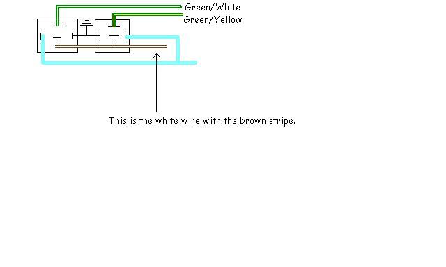
You will have to use 2 relays to replace one of these relays. The GREEN / WHITE and the GREEN/ YELLOW are connected together when the relay is energized, when the relay is at rest those 2 wires are not connected. I will draw you a picture. Might be later tonight or in the morning.
Don't forget to turn the Macro function off. It does not take good far away pictures when it is on.
Posted By: juvius
Date Posted: June 07, 2008 at 9:08 PM
no. they are all on there own pin. i think out of the new pictures there is a decent picture of the wires going to the pins.... the one pin where there isn't a wire going in has a tab that solders to the metal case wich in turn is grounded when the relay is screwed down onto the car.
Posted By: juvius
Date Posted: June 07, 2008 at 9:10 PM
ok.. sounds good. i really appreciate your help.
thanks again...
Posted By: i am an idiot
Date Posted: June 07, 2008 at 9:39 PM
The above picture will replace one of the older relays. You will have to build 2 of these.
Posted By: juvius
Date Posted: June 07, 2008 at 10:03 PM
thanks again.... once i get the sequential motor, i'll let you know how it works out.... have a great night
|