two voltages, one kill switch
Printed From: the12volt.com
Forum Name: Relays
Forum Discription: Relay Diagrams, SPDT Relays, SPST Relays, DPDT Relays, Latching Relays, etc.
URL: https://www.the12volt.com/installbay/forum_posts.asp?tid=106899
Printed Date: May 09, 2026 at 2:37 AM
Topic: two voltages, one kill switch
Posted By: blinky
Subject: two voltages, one kill switch
Date Posted: August 19, 2008 at 6:17 PM
This is for a robot project. I've got two sets of two 12v batteries for power. Two are 12v and two are 24v systems. I have a 12v relay and a 24v relay I want to wire a kill switch from both to cut power to main components. I was told to use a common ground but this proved disasterous as I discovered by accident. Long story short, I need at least one new battery now. I had grounds from both systems connecting across the two relays. Could someone help with an easy to follow guide as to how to wire these up correctly in keeping the two systems seperate and safe? Thank you kindly.
Replies:
Posted By: KPierson
Date Posted: August 19, 2008 at 6:47 PM
Why did the common ground not work? It should. Are you sure you hooked everything up correctly? I would use a DPDT or DPST switch - one switch, two isolated sets of contacts to keep the different voltages seperate. ------------- Kevin Pierson
Posted By: blinky
Date Posted: August 19, 2008 at 8:56 PM
thanks Kevin.
When a lead from the neg post on my 12v inadvertently touched the neg post on the 24v side, smoke and sparks ensued. I've been told this is due to having common grounds between the 12 and 24v relays. It made sense to me. It worked before but there's an open circuit created this way that's dangerous. Would the DPDT etc replace the relays? Would you have a part number for an appropriate switch with wiring tips to act as a my kill switch?
Posted By: blinky
Date Posted: August 19, 2008 at 9:42 PM
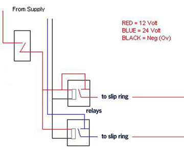
This is the diagram of my current setup.
Posted By: KPierson
Date Posted: August 19, 2008 at 10:09 PM
Honestly I don't quite follow what you are doing with the relays. Possibly a diagram that is a bit more detailed would help. Any DPDT switch that has contacts rated to hanle the current you are working with should do - I would connect them as close to each power supply as possible and cut the power at each set of batteries. ------------- Kevin Pierson
Posted By: blinky
Date Posted: August 19, 2008 at 10:15 PM
I'm using them to route power from batteries to components etc and create a way to cut said power. The box that says from supply on the drawing is the switch. Both 12 and 24 outputs go to a slipring, or did. Now they just go to a power distribution board. I want just one button to turn off both voltages.
Posted By: KPierson
Date Posted: August 19, 2008 at 10:33 PM
Gotcha, I thought the switch was the actual power supply. What you have in the drawing should work fine. If you go with a DPDT switch you would just wire the 24v line though the switch just like you did the 12v line. The DPDT switch is basically two isolated sets of switch contacts operated by the same switch lever. You should be able to wire the 24vdc in to the common of the switch and use the NO contact (or output) to feed the 24dc to the distribution board. You should be able to do the exact same thing with the 12vdc line, just like you have shown above. ------------- Kevin Pierson
Posted By: blinky
Date Posted: August 20, 2008 at 12:00 AM
Okay. Thanks for following through for me here.
Any idea why the 24v side re-acted so when a neg pole from the 12v came in contact with it? This is why I've since been warned about having common grounds with two separate voltages like this. There's really no reason for me to have common grounds in this particular case other than convenience.
Posted By: blinky
Date Posted: August 20, 2008 at 12:03 AM
Also one more detail. In your suggestion about the DPDT switch. Does that still include using the relays or just a switch with the proper rating? Thanks for all the help!
Posted By: KPierson
Date Posted: August 20, 2008 at 5:52 AM
If the relays are only there for isolation then you can replace them with the switch - the switch will provide the isolation. The only thing I can think of as to why the grounds would spark if you touched them is if the 12vdc and the 24vdc outputs were tied together somewhere. As long as you only tie one side of the power supply together (+ or -) you shouldn't have any problems. However, when you tie them both together with no load between them you'll have issues. Its very common to have a common ground system when working with multiple voltages - for example computers have a 5vdc and a 12vdc voltage going to all the optical drives and these voltages share a common ground. ------------- Kevin Pierson
Posted By: blinky
Date Posted: August 20, 2008 at 9:06 AM
Thanks again Kevin. You've been super helpful! I can't think of anywhere where the two voltages cross other than the relays. Hopefully the switch will solve the problem.
Darrell
|