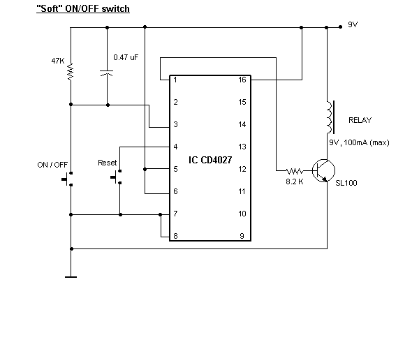
modify to work w/12v input and relay
Printed From: the12volt.com
Forum Name: Relays
Forum Discription: Relay Diagrams, SPDT Relays, SPST Relays, DPDT Relays, Latching Relays, etc.
URL: https://www.the12volt.com/installbay/forum_posts.asp?tid=107729
Printed Date: January 28, 2026 at 11:03 PM
Topic: modify to work w/12v input and relay
Posted By: masik
Subject: modify to work w/12v input and relay
Date Posted: September 26, 2008 at 4:11 PM
Would someone please modify this to work with 12V input and relay.
Thank you.

Replies:
Posted By: n2ixk
Date Posted: September 26, 2008 at 4:23 PM
Replace the relay with a unit having a 12V coil, and you should be good to go. CMOS logic chips (like the 4027) will operate over a pretty wide voltage range (typically 3 to 15V). I would suggest adding a suppressor diode across the relay coil to protect the transistor from spikes. A 1N4001 with the anode at the transistor end of the coil would do just fine.
What exactly is this circuit supposed to do? I can't see how a circuit using a relay output can function as a "soft" switch (assuming that means a device that slowly fades a light on and off).
Posted By: masik
Date Posted: September 26, 2008 at 4:51 PM
Thank you, I got the schematics of this website. https://electronicsworId.tripod.com/designimages/designckt1.html
Posted By: n2ixk
Date Posted: September 26, 2008 at 5:06 PM
OK, this is just what I thought it was--a "push on/push off" switch. Not really a "soft on/off" circuit at all.
BTW, you could eliminate the reset button by hanging an RC network from pin 4 to ground, and charging it with another resistor to +12V. That way, the reset pin is momentarily held "low" at power up, and the flip-flop starts in a predictable state.
Posted By: masik
Date Posted: September 27, 2008 at 5:34 PM
Just to make sure i'm reading the schematic right, bottom right going up the button is ground. And also to replace the reset button, you said just put a resistor instead. 6what size and its pin 4 through res to ground? Thanks
Posted By: masik
Date Posted: September 27, 2008 at 5:35 PM
bottom left sorry of the schematic
Posted By: n2ixk
Date Posted: September 27, 2008 at 6:23 PM
Yes, the symbol at the bottom left denotes ground (European notation).
To replace the reset switch, you need 3 components. First, a resistor and capacitor in parallel, from pin 4 to ground. .47uF and 10Kohm might be a good starting point. Then you need a separate resistor (1K might be a good start) from pin 4 to +12V. All of these values may need to be tweaked around to get a good reliable reset action. The only caveat is that the ratio of the 2 resistor values (which effectively form a series voltage divider) must be sufficient that the cap charges to a logical high at pin 4. At a Vdd of 13.8V, You will need around 11V or so.
What you are doing is forcing pin 4 to be held low by the initial charging of the capacitor when power is first applied, resetting the flip-flop. The cap charges through the 1K resistor until the voltage becomes a logical "high", at which time the flip-flop will function. The 10K resistor in parallel provides a discharge path for the capacitor when the circuit is powered down.
|
