latching relay with 2 seperate switches
Printed From: the12volt.com
Forum Name: Relays
Forum Discription: Relay Diagrams, SPDT Relays, SPST Relays, DPDT Relays, Latching Relays, etc.
URL: https://www.the12volt.com/installbay/forum_posts.asp?tid=111858
Printed Date: May 06, 2026 at 7:11 AM
Topic: latching relay with 2 seperate switches
Posted By: stevie12345
Subject: latching relay with 2 seperate switches
Date Posted: February 23, 2009 at 9:02 AM
Hi there, would like some help with the above, I would like a relay design that would give me 12 volt supply that latches on when one 12 volt pulse is received and then switches off when another 12 volt pulse is received. Any help would be appreciated, i did find something that latches on and off with a pulse, but what I want is "on" from one switch pulse and "off" from another switch pulse.
-------------
Thanks
Steve
Replies:
Posted By: KPierson
Date Posted: February 23, 2009 at 10:04 AM
That's a pretty easy one: 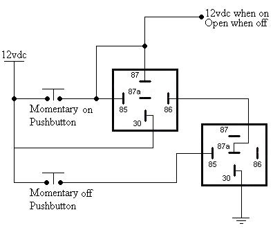
------------- Kevin Pierson
Posted By: stevie12345
Date Posted: February 23, 2009 at 10:20 AM
Thanks for reply, I dont think I have described what i want properly. What I need is a set up that allows me to energise a camera that has its own 12 volt supply, I would like it to be triggered on by a seperate 12 volt pulse and then switched off with another 12 volt pulse, ------------- Thanks
Steve
Posted By: KPierson
Date Posted: February 23, 2009 at 12:39 PM
The circuit above will do just that. Replace the "momentary switches" with your pulses and the 12vdc output will be what turns the camera on and off.
-------------
Kevin Pierson
Posted By: stevie12345
Date Posted: February 23, 2009 at 12:56 PM
Thanks again, I still have not been clear, the camera needs to run on its own 12 volt supply, completely seperate from the supply giving the pulses, I was thinking more of 12 volt latching relay or relays that could be activated with one pulse and de-activated with another. Hope this all makes sense.
-------------
Thanks
Steve
Posted By: KPierson
Date Posted: February 23, 2009 at 1:09 PM
Then control a third relay off the output of the circuit above. You would then essentially have a set of dry contacts to work with.
-------------
Kevin Pierson
Posted By: ckeeler
Date Posted: February 23, 2009 at 2:21 PM
you also could just use a single relay. you would need a latching type relay thats has dual coils rather than a single coil.
Posted By: howie ll
Date Posted: February 23, 2009 at 5:14 PM
CK has the answer, and if you hang on, I'll post you back with the Maplin UK part number once I get back to discussing beer with KP and finishing my emails, 'cause it's 11:15, I've just got back from a 230 mile round trip, reading up on Spurs' win and having a cup of tea and a ciggie.
Posted By: howie ll
Date Posted: February 23, 2009 at 5:49 PM
As promised Maplin Electronics, 2Amp rating DPDT latching relay, Maplin part number N38 AW about £3.50
Posted By: KPierson
Date Posted: February 23, 2009 at 6:01 PM
The dual coil latching relay would definately simplify things! Good call guys.
-------------
Kevin Pierson
Posted By: i am an idiot
Date Posted: February 23, 2009 at 7:54 PM
There is no connection to 86 on the relay to the right.
Posted By: ckeeler
Date Posted: February 23, 2009 at 7:59 PM
good eye! i didnt even notice that. 
Posted By: i am an idiot
Date Posted: February 23, 2009 at 8:02 PM
It needs to be grounded, if anyone is going to use it.
Posted By: KPierson
Date Posted: February 23, 2009 at 8:04 PM
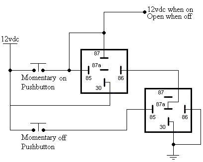
Good eye, I need to quit drawing pictures early in the morning after no sleep! ------------- Kevin Pierson
Posted By: howie ll
Date Posted: February 24, 2009 at 3:08 AM
Fine, lovely will you stop making 86 the neg side of the bloody coil? When the Germans first used those relays in the 70s they had the DIN number codes for everything, later become ISO motor industry codes which is why say ABS or airbag or parking brake lights look the same on every car, that's how we get the relay numbers, other things like power side 30, lighting 55 on, ground 31, Ignition 15 etc etc
Posted By: i am an idiot
Date Posted: February 24, 2009 at 3:28 AM
We received the Relays but the documentation must have fallen overboard.
Posted By: howie ll
Date Posted: February 24, 2009 at 5:20 AM
Ah some one else as anal as me! Sorry about being pedantic but you're the ones who crashed a Martian lander because the software mixed up metric and imperial....... 
Posted By: KPierson
Date Posted: February 24, 2009 at 5:44 AM
i am an idiot wrote:
We received the Relays but the documentation must have fallen overboard.
I can not go by that documentation simply because it states Pin 30 is the "INPUT" from battery and Pin 87 is simply "INPUT". How can that be possible, since they are connected wouldn't one of them have to be an output? Silly Germans. Haha ------------- Kevin Pierson
Posted By: howie ll
Date Posted: February 24, 2009 at 7:34 AM
Craig, Kevin what have I started now? Can we all take our tongues out of our cheecks and admit 87 and 30 might be interchangeable? Convention on original non changeover relays i.e. 4 pin no 87a was that 30 was input and 87 was output, of course as an immob or change over for use in locking...we have 30 as output and 87 + 85 or 86 depending on polarity as input. OK I promise to stop being so pedantic in future.
Posted By: KPierson
Date Posted: February 24, 2009 at 8:42 AM
I'm am willing to admit it as long as you are willing to admit 85 and 86 are interchangable! All kidding aside, that document was pretty informative - I never realized there were "standards" covering the pins. ------------- Kevin Pierson
Posted By: ckeeler
Date Posted: February 24, 2009 at 8:49 AM
no Howie, dont stop. we need more of that at times and besides, i get a kick out of it. Howie would just not be Howie without it...... 
Posted By: KPierson
Date Posted: February 24, 2009 at 10:29 AM
Yeah, random tidbits of solid information are always appreciated. I may even change my relay diagram to reflect the changes. I always ground pin 86 because I draw from left to right and when I made the relay bitmap I made it in numerical order. If I swapped the 85 and the 86 in my original template it would more then likely fix all my drawings moving forward. ------------- Kevin Pierson
Posted By: Ween
Date Posted: February 24, 2009 at 12:19 PM
hi, my two cents... 86 and 85 are interchangeable, as long as you don't have an ISO style relay with a suppression diode built in. whatever you may connect that relay upto may not like the outcome the first time it's operated. and yes term 86 i always wire to the positive supply/source. m running with sissors 'cause i can
Posted By: stevie12345
Date Posted: February 25, 2009 at 3:26 AM
Hi everyone and well done to Spurs, I have ordered the latching coil from Maplins and will have a go with that, will let you know how I get on.
-------------
Thanks
Steve
|