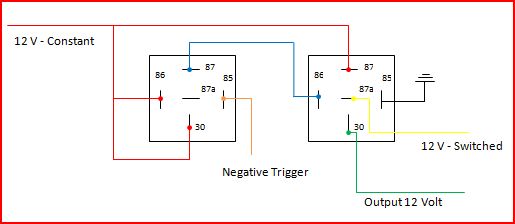
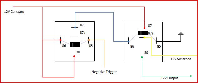
relay diagram for car pc
Printed From: the12volt.comForum Name: Relays
Forum Discription: Relay Diagrams, SPDT Relays, SPST Relays, DPDT Relays, Latching Relays, etc.
URL: https://www.the12volt.com/installbay/forum_posts.asp?tid=111914
Printed Date: May 06, 2026 at 9:13 AM
Topic: relay diagram for car pc
Posted By: rsa_sean
Subject: relay diagram for car pc
Date Posted: February 25, 2009 at 10:35 AM
Replies:
Posted By: KPierson
Date Posted: February 25, 2009 at 11:28 AM
Posted By: rsa_sean
Date Posted: February 25, 2009 at 12:35 PM
Posted By: rsa_sean
Date Posted: February 25, 2009 at 12:37 PM
Posted By: KPierson
Date Posted: February 25, 2009 at 3:45 PM
Posted By: rsa_sean
Date Posted: February 26, 2009 at 7:39 PM
Posted By: KPierson
Date Posted: February 26, 2009 at 8:17 PM