Hi All,
I want to turn on a few accessories that I am installing in my 06 BMW X5.
A navigation screen video interface, which which requires 12vdc, 1 amp.
A multimedia player, which requires 12vdc, 1.5amps
I would like to use the remote turn on wire to trigger a relay to supply power to these accessories so that they turn on.
I know this has been probably covered on the forums, but I can find a defitine post on how to hook this up.
Here are some questions I have:
Do I hook up the the relay on the coil in-line with the remote turn-on wire going to my amp? or do I just tap into the wire and connect to one end of the coil and the other to ground?
On the other side of the realy, would I connected both accessories positive lead on one end and the other to ground?
Should I put in a fuse from the 12v constant source to the relay or individual fuses from relay to accessories?
I have also read about adding a diode to the relay? Is it recommended?
I am very handy with a soldering iron and following schematics. Just a bit scared of doing a wrong connection and burning something out in my car.
Thanks for any help you guys can provide.
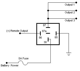
Using a standard relay:
Pin 85 = Ground.
Pin 86 = Remote turn on from head unit. Just tap into wire without cutting.
Pin 87 = To power inputs of added components (navi and multimedia).
Pin 30 = Power feed from vehicle. Install a 5 amp inline fuse.
-------------
Prepare your future. It wasn't the lack of stones that killed the stone age.
Awesome, thanks. Just wanted to make sure.
I would put a coil across the relay - remote outputs aren't guarenteed to be designed for inductive loads (since most applications don't involve a relay). The diode is a $0.10 part that protects the output on your deck, it really wouldn't make sense not to put one in.
For the remote wire to your amp you could do it two ways - you could simply tap pin 86 without cutting the remote wire or you could cut the remote wire, wire the head unit side of the cut wire to pin 86 and then add the amp side of the wire to the accessory output of the relay. The second situation would leave you with only the relay being powered by the deck, and all accessories being powered through the 5A fuse going through the relay as suggested above. If you were to have a problem with the remote wire somehow shorting out the 5A fuse would blow and your deck's output would be isolated from the incident. If it were me, I would wire it the 2nd way for the added protection of the isolation.
-------------
Kevin Pierson
Mr. Pierson,
Thank you for your reply. I would like to be as safe as possible. Would you be so kind and/or capable to provide me some type of schematic so that I can visualize the connections you are referring to.
Thank you for your help.
Thank you very much for the schematic.
Mr. Pierson, if you have the time, how would the coil & diode(s) you recommended be added for extra safety be connected to this circuit, and of what type and measurements should they be?
Thank you for all your help.
Sorry, I meant to add the diode but I got distracted before I uploaded the picture and I forgot.
You can use a 1A diode found at Radioshack. The striped end of the diode goes to pin 86 and the non striped side goes to pin 85.
The "coil" is internal to the relay, you don't need to add a second one. The coil is internally connected to Pin 85 and Pin 86. When you run voltage through this coil it creates a magnetic field that causes the contacts inside the relay to swich positions. When you take voltage away from the coil the magnetic field collapses a voltage spike is created. The diode allows the spike to be suppressed to ground instead of back to the 12vdc line.
-------------
Kevin Pierson
Thats definately pretty cool!
As far as a PCB you can make your own!
www.FreePCB.com is a great free circuit board editor. I've used it for multiple problems and I've never had any issues with it. It doesn't have an "auto router" so you have to basically make the entire circuit board manually.
Once the board is laid out you can upload the Gerber files to www.4pcb.com and get "barebone" prototype boards for dirt cheap in a matter of days. I just ordered some boards from there this week for a project of similar size and 10 boards were $6.50 a piece.
The "big" problem here is soldering the PLCC44 chip. I'm not sure if it could be done by hand, you may need a reflow oven. I would contact the author of the project and see if he has any boards with chips laying around!
-------------
Kevin Pierson