how to test relay from jbl amplifier?
Printed From: the12volt.com
Forum Name: Relays
Forum Discription: Relay Diagrams, SPDT Relays, SPST Relays, DPDT Relays, Latching Relays, etc.
URL: https://www.the12volt.com/installbay/forum_posts.asp?tid=113274
Printed Date: April 18, 2026 at 6:59 PM
Topic: how to test relay from jbl amplifier?
Posted By: craig155
Subject: how to test relay from jbl amplifier?
Date Posted: April 19, 2009 at 5:18 PM
Can anyone tell me how to test this relay, it came out of a jbl amplifier. Thanks. Craig.

Replies:
Posted By: craig155
Date Posted: April 19, 2009 at 5:19 PM
another picture. 
Posted By: i am an idiot
Date Posted: April 19, 2009 at 5:40 PM
Using an Ohm meter, one of the larger terminals will be connected directly to another of the larger terminals. See the 2 smaller terminals with the squiggly line connecting them? Those are the coil of the relay. Apply 12 volts to one and ground to the other and it should make a clicking sound. remove one wire and it should click again. With it energized, The third larger terminal should now be connected to one of the 2 that were connected earlier. Whichever one is now connected to the 3rd one is the common connection. The 3rd terminal is the normally open connection. Tho only other one left is the normally closed connection. Those relays are extremely reliable. Why do you think it is bad? What exactly is the amp doing or not doing to lead you to believe it is broken?
Posted By: howie ll
Date Posted: April 19, 2009 at 7:17 PM
The shape's wrong but it's a standard configuration with the top right as 87, top left as 87a and centre bottom is 30. Sanyou?
Posted By: craig155
Date Posted: April 20, 2009 at 4:54 PM
Originally the amp blew 2 caps which i replaced but the amp is still in safe mode and i suppose i am clutching at straws. The blown caps were at position c102 and c108. Since these photos were taken i took out the ceramic ones and put in the correct ones. Any ideas guys? Craig.

Posted By: craig155
Date Posted: April 20, 2009 at 4:55 PM
Posted By: i am an idiot
Date Posted: April 20, 2009 at 5:28 PM
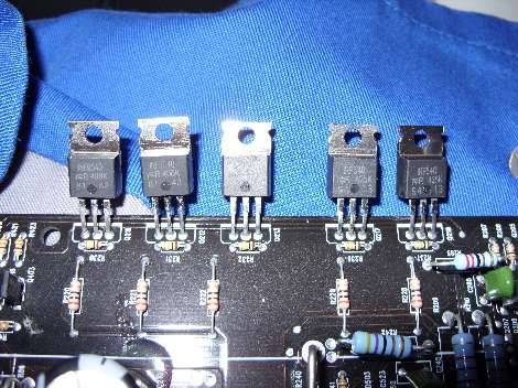
Chances are you have shorted output transistors. Can you take a photo of the entire circuit board so I can show you where the output transistors are located.
Posted By: craig155
Date Posted: April 23, 2009 at 3:14 PM
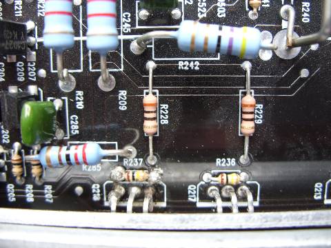
Here are a couple of photos:  
Posted By: i am an idiot
Date Posted: April 23, 2009 at 4:30 PM
transistors on the left side of the amp. What are the numbers on them? The 7 at top of picture. The 4 at the bottom of the picture.
Posted By: craig155
Date Posted: April 23, 2009 at 5:48 PM
Posted By: craig155
Date Posted: April 23, 2009 at 5:49 PM
Posted By: craig155
Date Posted: April 23, 2009 at 5:49 PM
Hope these are readible
Posted By: i am an idiot
Date Posted: April 23, 2009 at 8:41 PM
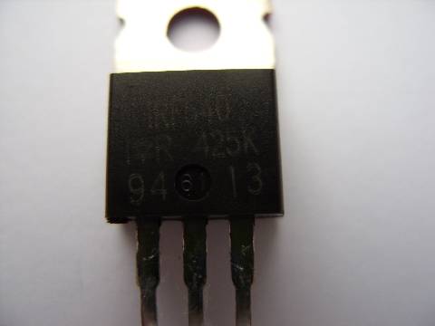
Yes they are legible. The ones labeled IRF-540 are the outputs. Do you have a digital meter? Do you know where the diode test function is located on the meter?  is the symbol for a diode. The diode test function should have a similar symbol. is the symbol for a diode. The diode test function should have a similar symbol.
Posted By: craig155
Date Posted: April 24, 2009 at 7:15 PM
yes, i have seen a similar post that you have helped with, i will post the readings shortly.
Posted By: i am an idiot
Date Posted: April 24, 2009 at 9:04 PM
Do not pull the transistors out of the board. Chances are there is only one on each side that is actually shorted. You will need to replace all associated with the one that shorted. They all went through the same abuse, the ones that did not fail are more than likely weak and will not hold up. After you locate the shorted one or 2, you can remove them and see if the amp works. Do not play it loud or long, we just need to see if that is the only damage.
To check them, one meter lead on the metal case of the transistor, the other lead to the right leg of the transistor. If it reads near a dead short, one of the ones in that bank is shorted. To find the shorted one, move the lead from the right leg to the left leg. Check all of them and notice the readings. One will read lower than the rest. That one is shorted. Remove it and check the ones on the other side. Remove the shorted one there too. Make sure there are no solder bridges on the ones you removed. It really needs to be put back in the heat sink and all transistors clamped down when testing it. Remove all fuses on the amp and place a single 10 amp fuse for testing.
Posted By: craig155
Date Posted: April 25, 2009 at 9:53 AM
With the board facing up and the phonos to the right, the readings are 493/514 491/513 these are the top ones. the bottom two are 483/1018 489/1029, do these figure make sense? Thanks for the help by the way
Posted By: craig155
Date Posted: April 25, 2009 at 10:14 AM
If i have 1 lead on the left leg and the other on the right leg i get a buzzer sound from the multimeter, this happens on the 2 top transistors and accross the resistors? at their base. Are these the defective ones?
Posted By: i am an idiot
Date Posted: April 25, 2009 at 9:51 PM
How many 540s are there on each side of the amp?
Posted By: craig155
Date Posted: April 26, 2009 at 7:07 AM
There are 2 540's on each side of the board and 3 9540's on each side.
Posted By: i am an idiot
Date Posted: April 26, 2009 at 7:50 AM
Check each of the 540s and 9540s as follows. Red meter lead on metal tab of transistor, black lead on the right leg. Let me know how many of what type are reading near 0.000 on the meter. When it was buzzing at you the way you tested it earlier, what was the meter reading at that time?
Posted By: craig155
Date Posted: April 26, 2009 at 4:53 PM
None are reading near zero, the 540s are showing 1222. When it was buzzing, they were showing 030.
Posted By: i am an idiot
Date Posted: April 26, 2009 at 5:29 PM
It is rare for them to short from leg 1 to leg 3. But it does happen. You will have to remove those 2 to test them further. To remove them, heat the joints up and add extra solder to all 3 joints on each part. Now lay your iron across all 3 joints and the transistor should fall out of the board. If it does not fall out, use some small pliers and gently pull the part out of the board. The pliers are only so you do not burn your fingers. Do not force them out with the pliers. Check them again from left leg to right leg. Let me know what you find out.
Posted By: craig155
Date Posted: April 26, 2009 at 5:56 PM
removed the 2 540s and checked leg 1 & 3 no buzzer, meter stayed showing 1. I also removed the 2 resistors and they did not buzz either. The funny thing is that i checked the joints that the transistors and resistors came out of and they made the multimeter buzz. Any idas?
Posted By: i am an idiot
Date Posted: April 26, 2009 at 6:12 PM
Check the transistors on the other side of the board the same way.
Posted By: craig155
Date Posted: April 26, 2009 at 6:17 PM
same readings
Posted By: i am an idiot
Date Posted: April 26, 2009 at 7:19 PM
Are you sure that they are IRF-540 or IRF-9540? The rectifier diodes will read like that when in circuit. If they are 540 or 9540, remove them and test out of circuit.
Posted By: craig155
Date Posted: April 27, 2009 at 12:07 PM
They are definately IRF 540 and IRF 9540. With the black lead on the metal body if you then touch the right leg you get a reading,if you then touch the left leg the meter stays showing 1. If you then touch the right leg again the buzzer sounds. This happens on both transistors. If you leave them for a couple of minutes the same as above happens.
Posted By: craig155
Date Posted: April 27, 2009 at 12:16 PM
Posted By: craig155
Date Posted: April 27, 2009 at 12:17 PM
Posted By: i am an idiot
Date Posted: April 27, 2009 at 3:24 PM
That is how they are supposed to work. Once you touch the lead to the left leg, you turn the transistor on. It will remain on until you turn it off by holding the red lead to the case and touching the black lead to the left leg. You stated that from left leg to right leg it read .030, what happened with that? Chack the board from left hole to right hole. I can tell nothing by learning of a buzz from your meter. I need to know numbers from here on out.
Posted By: craig155
Date Posted: April 27, 2009 at 3:47 PM
With the red lead on the case and black lead to the right leg I am not getting any reading. Red lead on case,black lead on left leg i am not getting any reading.
Posted By: craig155
Date Posted: April 27, 2009 at 4:01 PM
I checked the board, red lead in centre hole and black lead in left hole and got a reading 1100+. Putting the black lead in right hole getting reading 1100+
Posted By: i am an idiot
Date Posted: April 27, 2009 at 4:16 PM
Those outputs are fine. Put them back in the board. On an N channel FET, red lead on case will give no reading at all. Black lead on case, red lead on right leg should read around .400 to .600 depending on your meter. Once you check the left leg with the red lead, it turns the transistor on and then if you recheck the right leg, it should read much nearer .000 ..040 to 180 depending on the transistor and your meter.
Posted By: craig155
Date Posted: April 27, 2009 at 4:21 PM
So does that mean the transistors are ok then? How do i test the small resistor at the base of the transisitor?
Posted By: craig155
Date Posted: April 27, 2009 at 4:27 PM
With transistor turned on,right leg shows 128 on one and 508 on the other.
Posted By: i am an idiot
Date Posted: April 27, 2009 at 4:33 PM
Those outputs are fine. Put them back in the board. What are the colors of the bands on the resistor? With your meter set to Ohms, one lead on one end of the resistor, other lead on the other end of the resistor, notice the reading on the meter. Also notice if there are any letters displayed on the meter. K or M specifically.
Posted By: craig155
Date Posted: April 27, 2009 at 4:40 PM
with meter set to 2M (Ohms) getting a reading of 0.98. it is a carbon film 1/5 wj 100 Ohm resistor
Posted By: i am an idiot
Date Posted: April 27, 2009 at 4:46 PM
Does your meter have a 200 ohm setting? If so set it there and check it again. But from what I am gathering with the meter set to the 2Meg scale. I would assume that the resistor is reading 98 ohms.
Posted By: craig155
Date Posted: April 27, 2009 at 4:49 PM
with it set to 200 i cannot get it to register anything
Posted By: i am an idiot
Date Posted: April 27, 2009 at 4:59 PM
If they are supposed to be 100 ohm resistors, they should read 100 with the meter set to the 200 Ohm setting. What color are the bands on the resistor?
Posted By: craig155
Date Posted: April 27, 2009 at 5:07 PM
Posted By: craig155
Date Posted: April 27, 2009 at 5:12 PM
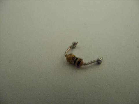
brown,black,yellow,gold?
Posted By: craig155
Date Posted: April 27, 2009 at 5:14 PM
looking at the blown up pictur it looks like a piece of ceramic is missing of the resistor?
Posted By: i am an idiot
Date Posted: April 27, 2009 at 5:58 PM
That is a 100,000 Ohm resistor. Brown = 1 Black = 0 Yellow = the number of 0s to put on the end. Yellow =4 1 0 0000 = 100K ohms. I am sure it is fine, it was reading 98 so I assume that it is 98,000 ohms.
Posted By: i am an idiot
Date Posted: April 27, 2009 at 6:03 PM
Are you sure the third band is yellow? That resistor looks damaged, in order to damage a 100K ohm resistor, there would have to be way more voltage than that amp is capable of producing. Is that resistor connected to the left leg of the transistor?
Posted By: craig155
Date Posted: April 27, 2009 at 6:11 PM
Yes, just checked the schematic and it is indeed a 100k Ohm resistor. On one of the transistors the left leg is cracked so i think i will get 4 new ones and put them in the board, then hopefully you can advise on where to look next. If you dont mind of course. Its getting late here now, just after midnight, so i think its time for bed. Will be on again tomorrow, catch you then?
Posted By: i am an idiot
Date Posted: April 27, 2009 at 7:18 PM
If the left leg of one of the transistors is broken, that is your problem. The transistor is turning on and the amp thinks it is shorted. That is why it is in protect.
Posted By: craig155
Date Posted: April 28, 2009 at 8:13 AM
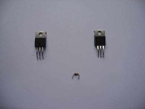
Fitted new transistors and refitted resistor, put everything back together, connected to power source including remote and proection lights still on. Does it make a difference as i have just connected +ive and remote to car battery on bench? I have not connected phonos, speaker wires.
Posted By: craig155
Date Posted: April 28, 2009 at 8:26 AM
Posted By: craig155
Date Posted: April 28, 2009 at 8:28 AM
the above picture shows the new transistors and the old resistor before it was replaced.
Posted By: craig155
Date Posted: April 28, 2009 at 8:31 AM
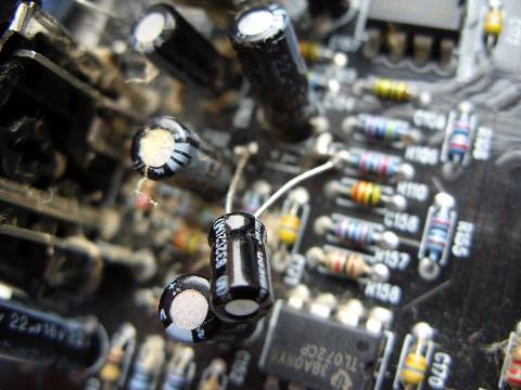
Posted By: craig155
Date Posted: April 28, 2009 at 8:40 AM
the above photo shows the electrolytic capacitors that were a direct replacement for the ones that blew in the first instance (10uf 16v) The strange thing is that if you look at the board and according to the schematic i have they should be capacitor ceramic tubular 102pf 50v?
Posted By: i am an idiot
Date Posted: April 28, 2009 at 8:53 AM
You need to check the voltage across the capacitor. If there is more than 16 volts across it, that is probbly why the first ones exploded.
Posted By: craig155
Date Posted: April 28, 2009 at 9:07 AM
is there much of a differce between 102uf and 10pf?
Posted By: craig155
Date Posted: April 28, 2009 at 9:15 AM
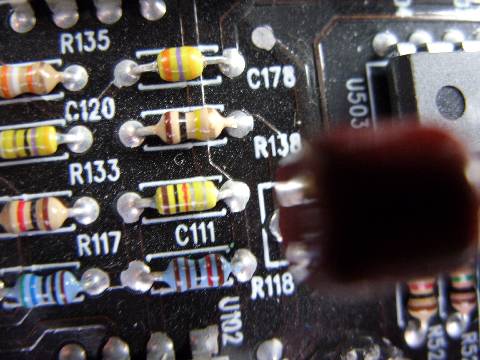
Posted By: craig155
Date Posted: April 28, 2009 at 9:17 AM
C111 are, according to the schematic what should be where the electrolytics are.
Posted By: KPierson
Date Posted: April 28, 2009 at 9:22 AM
craig155 wrote:
is there much of a differece between 102uf and 10pf?
102uf = 1000uf = 0.001000 f (micro =10^-6) 10pf = 10pf = 0.000000000010 f (pico =10^-12) If they were planets one would be Venus and the other would be Neptune. ------------- Kevin Pierson
Posted By: craig155
Date Posted: April 28, 2009 at 9:25 AM
so, this will never work with these parts in then?
|