banging my head, 1 wire, 2 functions
Printed From: the12volt.com
Forum Name: Relays
Forum Discription: Relay Diagrams, SPDT Relays, SPST Relays, DPDT Relays, Latching Relays, etc.
URL: https://www.the12volt.com/installbay/forum_posts.asp?tid=113459
Printed Date: April 18, 2026 at 8:44 AM
Topic: banging my head, 1 wire, 2 functions
Posted By: djfearny2
Subject: banging my head, 1 wire, 2 functions
Date Posted: April 27, 2009 at 9:51 PM
Whats up peeps.
here is the deal. I have a dodge magnum and have installed steering wheel shifting thru the clockspring. easy now heres the delema. my car did not come with steering wheels controls so I bought some and modded them to use them just for the buttons.
anyway the two outside switches are used to control my shifting up and down.
but here is the twist I only have two wires and i want to use one wire for two functions IE: when one button is pressed it is a negative trigger and shifts, when another button is pressed it throws a possitve trigger and triggers my train horns.
getting the wire to reverse polarity is easy. and done. here is my issue tho,. I need to wire two relays one for a negative to negative throw and the other for a possitve to possitive throw.
wiring the relays are not the issue but not getting feedback is.
I am wiring the relays like this
Negative
pin 85 neg input
pin 86 pos
pin 87 neg
pin 30 output to shifter neg
pos
pin 85 ground
pin 86 pos input
pin 87 pos
pin 30 output to pos train horn valve,.
Im getting feedback becuase the train horn relay has a rest at ground which is feeding back thru to the negative relay
I am trying to get rid of the feedback how can i go about doing this. shall i be doing the 1 k cap, and 10k reistor for the triggers? or can someone chime in.
remember both inputs are wired together to one wire comming from the steering wheel. and the rest at ground is killing me
-------------
Jon
Installer/Help Technician
---coral springs florida---
mecp certification is not always needed. I have it and it has not helped me out at all. my experience out shines it.
Replies:
Posted By: KPierson
Date Posted: April 27, 2009 at 11:03 PM
The issue is obviously the fact that you basically have two resistors (the relay coils) wired in series. One way to eliminate that is to add transistors. You can add a PNP ((+) switches it on) and an NPN ((-) switches it on) transistor and then wire the relays to fire off the transistors. The transistors will isolate one coil from the other and thus eliminate the feedback. ------------- Kevin Pierson
Posted By: hotwaterwizard
Date Posted: April 28, 2009 at 12:49 AM
 ------------- John DeRosa (Hotwaterwizard)
Stockton California
When in doubt, try it out !
Posted By: i am an idiot
Date Posted: April 28, 2009 at 3:30 AM
Notice the Numbers on the relays. The numbers are correct, their orientation with the actual layout of the relay is not correct. I would use 1n4001 diodes.
Posted By: djfearny2
Date Posted: April 28, 2009 at 8:24 AM
What kind of transistors, Can you log onto radioshacks website and get me a part number or two or three,.
AS for the relay diagram Ihave done the diode across the coil pols and feeback is still there.
Ill try it with different relays since the ones i am using have a built in resistor.
-------------
Jon
Installer/Help Technician
---coral springs florida---
mecp certification is not always needed. I have it and it has not helped me out at all. my experience out shines it.
Posted By: KPierson
Date Posted: April 28, 2009 at 9:17 AM
2n3904 for the NPN and 2n3906 for the PNP 
Obviously a bit more complicated then using diodes alone. ------------- Kevin Pierson
Posted By: djfearny2
Date Posted: April 28, 2009 at 12:43 PM
hey KP
is the diode on r2 backwords or meant to be that way?
-------------
Jon
Installer/Help Technician
---coral springs florida---
mecp certification is not always needed. I have it and it has not helped me out at all. my experience out shines it.
Posted By: i am an idiot
Date Posted: April 28, 2009 at 12:54 PM
He meant to draw it that way to see if you were paying attention. You passed. It is backwards.
Posted By: KPierson
Date Posted: April 28, 2009 at 1:09 PM
Yep, I messed up, sorry!
-------------
Kevin Pierson
Posted By: djfearny2
Date Posted: April 28, 2009 at 1:52 PM
the only problem i am having is this. remember the two inputs need to be connected together and then connect to a single wire.
that wire throws possitive thru one button and negative thru another on the same wire. when i twist the two inputs together the realys activate. and before I twist the two together it take the opposite signal to activate. Ie relay 1 is supposed to be neg out yet it needs a pos signal to activate. thru the transistor.
-------------
Jon
Installer/Help Technician
---coral springs florida---
mecp certification is not always needed. I have it and it has not helped me out at all. my experience out shines it.
Posted By: KPierson
Date Posted: April 28, 2009 at 2:21 PM
In the diagram above the 3906 will turn on when a - voltage is applied and the 3904 will turn on when a + voltage is applied to the base. The transistors collector output is inversed from the base input - I'm guessing that is why you think it is backwards. When you twist the wires together do both relays activate or just one? Is this with or without the switch wire connected? When I get home tonight I'll try to build the circuit and see what kind of results I get. ------------- Kevin Pierson
Posted By: djfearny2
Date Posted: April 28, 2009 at 2:40 PM
both relays activate, and ok ill modify the relay setup
-------------
Jon
Installer/Help Technician
---coral springs florida---
mecp certification is not always needed. I have it and it has not helped me out at all. my experience out shines it.
Posted By: djfearny2
Date Posted: April 28, 2009 at 2:59 PM
and ok so the 3096 needs neg to activate so shall i have that one controlling the relay that uses a negative input to negative output? cause the signals dont change the shifter is neg so i have the switch set up to throw neg and the air horns are pos so again the other switch is setup to throw pos.
-------------
Jon
Installer/Help Technician
---coral springs florida---
mecp certification is not always needed. I have it and it has not helped me out at all. my experience out shines it.
Posted By: i am an idiot
Date Posted: April 28, 2009 at 3:13 PM
KPierson wrote:
Yep, I messed up, sorry!
I gave you an out.
Posted By: KPierson
Date Posted: April 28, 2009 at 4:11 PM
i am an idiot wrote:
KPierson wrote:
Yep, I messed up, sorry!
I gave you an out.
haha, thanks. I guess I'm just so used to messing things up it doesn't bother me at all anymore to admit it. ------------- Kevin Pierson
Posted By: KPierson
Date Posted: April 28, 2009 at 4:13 PM
djfearny2 wrote:
and ok so the 3096 needs neg to activate so shall i have that one controlling the relay that uses a negative input to negative output? cause the signals dont change the shifter is neg so i have the switch set up to throw neg and the air horns are pos so again the other switch is setup to throw pos.
I'm not exactly sure what you are saying here. I think what you are asking is if you should run a ground through the relay that uses the 3906 because it needs a ground to switch and the answer is it doesn't matter. The coil and the contacts are completely isolate so you can run anything you want through each set of contacts. ------------- Kevin Pierson
Posted By: djfearny2
Date Posted: April 28, 2009 at 5:19 PM
ok thanks, and if you can build the setup and see what you get and see if it stacks up to what my outcome has been.
and yes twisting the two inputs together Both relays activate.
let me ask you this..
is there a way to do this without relays as the output does not have to be high current. for either device to work properly.
-------------
Jon
Installer/Help Technician
---coral springs florida---
mecp certification is not always needed. I have it and it has not helped me out at all. my experience out shines it.
Posted By: djfearny2
Date Posted: April 28, 2009 at 5:19 PM
btw thanks for helping thus far.
-------------
Jon
Installer/Help Technician
---coral springs florida---
mecp certification is not always needed. I have it and it has not helped me out at all. my experience out shines it.
Posted By: KPierson
Date Posted: April 28, 2009 at 8:11 PM
I hooked it up here at home and I got the same results - it works great until you tie the bases together. That got me looking at the diagram and we actually have the same problem - voltage is backfeeding through the top transistor out the base in to the 2nd transistor. I appologize for not catching that when I drew it up. I'll keep messing with it and see what I come up with. ------------- Kevin Pierson
Posted By: djfearny2
Date Posted: April 28, 2009 at 8:28 PM
thanks alot keep me posted.
-------------
Jon
Installer/Help Technician
---coral springs florida---
mecp certification is not always needed. I have it and it has not helped me out at all. my experience out shines it.
Posted By: KPierson
Date Posted: April 28, 2009 at 9:00 PM
I don't know how involved you are willing to get with this, but I have another idea that involves using an op amp as a two voltage followers. The outputs of the op amps can then drive the transistors above. Have you tried the relay diagram with the diodes? If that works that would be quite a bit simpler. ------------- Kevin Pierson
Posted By: i am an idiot
Date Posted: April 28, 2009 at 9:11 PM
If you do try the relays, the numbers are correct on the relays. However the layout is not correct. Do not make the circuit look as it does in the picture.
Posted By: djfearny2
Date Posted: April 28, 2009 at 10:56 PM
im into it until it is accomplished.
I have a dodge and they are notorious for multiplex systems. one wire with multible functions via ground resistance. I can wire the switches for anything i need or want. Do you or anyone know of a system or setup that can be done to create a multiplex system.
-------------
Jon
Installer/Help Technician
---coral springs florida---
mecp certification is not always needed. I have it and it has not helped me out at all. my experience out shines it.
Posted By: djfearny2
Date Posted: April 28, 2009 at 10:58 PM
I know the pin outs on relays without even thinking about it anymore so I read it as numbers anyway. BUt i did try it and didnt get anywhere. will again try anything.,
-------------
Jon
Installer/Help Technician
---coral springs florida---
mecp certification is not always needed. I have it and it has not helped me out at all. my experience out shines it.
Posted By: KPierson
Date Posted: April 29, 2009 at 6:03 AM
djfearny2 wrote:
im into it until it is accomplished.
I have a dodge and they are notorious for multiplex systems. one wire with multible functions via ground resistance. I can wire the switches for anything i need or want. Do you or anyone know of a system or setup that can be done to create a multiplex system.
Multiplexing gets a bit more involved and can be done in several ways. For a voltage multiplex you can use a microcontroller with analog to digital converter or you can use op amps set up as voltage comparators. I've personally done it both ways and it worked both ways. When I went the op amp route I used to op amps for each multiplex input and created a voltage "window". Since you are only using battery voltage and ground I think it can be done with one op amp chip (with multiple op amps on it). I'll try to draw something up later today. ------------- Kevin Pierson
Posted By: djfearny2
Date Posted: April 29, 2009 at 7:16 AM
thnanks again if possible please include part numbers.
-------------
Jon
Installer/Help Technician
---coral springs florida---
mecp certification is not always needed. I have it and it has not helped me out at all. my experience out shines it.
Posted By: djfearny2
Date Posted: April 30, 2009 at 1:44 PM
im guessing no luck or time.
-------------
Jon
Installer/Help Technician
---coral springs florida---
mecp certification is not always needed. I have it and it has not helped me out at all. my experience out shines it.
Posted By: KPierson
Date Posted: April 30, 2009 at 2:44 PM
I would give this a shot. The op amp (available at Radioshack stores) should provide isolation between the transistor bases. The op amp will be set up as a "voltage follower" on both channels and will output whatever you put in to it. So, Pin 1 and Pin 7 will mimic your wire coming from the steering wheel. The seperate, isolated channels should stop any feedback. ------------- Kevin Pierson
Posted By: djfearny2
Date Posted: April 30, 2009 at 10:40 PM
can you tell me how i determine the propper pin outs on the op chip. There is no significant marking except a dot more or less to determine orientation.
-------------
Jon
Installer/Help Technician
---coral springs florida---
mecp certification is not always needed. I have it and it has not helped me out at all. my experience out shines it.
Posted By: i am an idiot
Date Posted: April 30, 2009 at 10:43 PM
The Dot is pin 1. Also, the horseshoe shaped notch in the top of the picture above indicates pin 1. All integrated circuits have one or both of the markings described.
Posted By: dualsport
Date Posted: May 02, 2009 at 10:10 PM
Is there supposed to be a quiescent condition where neither relay is on?
If the input is left floating what is going to happen with the relays?
Posted By: dualsport
Date Posted: May 02, 2009 at 10:25 PM
I'd suggest adding zener diodes on the original transistor drive circuit to provide isolation in the inactive condition where neither relay is supposed to be energized.
Put them in series with the base of the transistors, and put the base resistor in the input from the steering wheel wire.
When the input is open, the two zener diodes in series will not conduct (select a value of 6V or so), since they'll below 12V.
When you have an active input of 12V or ground, the corresponding zener will begin to conduct since it'll have 12V across the single zener, and provide the current to the transistor driver stage.
Posted By: t&t tech
Date Posted: May 02, 2009 at 11:09 PM
at the risk of sounding stupid i'm gonna ask a question, feel free to criticize me, would wiring the trigger with the same polarity make this problem go away, since he's using relays i mean, does he really need a negative and a positive signal, if he were to just use a straight negative signal to activate both relays one would be going negative to negative and the other inverting from negative to positive, or the other way positive signal triggering both relays, or would there still be feedback ?, or is this too simple and i don't know what i'm saying, again feel free to criticize.
-------------
Posted By: dualsport
Date Posted: May 02, 2009 at 11:48 PM
There's two different functions he's trying to control with a single wire, and probably aren't supposed to happen at the same time.
To individually control the two functions means there has to be a different signal to trigger each one. In this case, one is a +12V positive signal, and the other is a negative going ground switch signal.
When neither one is active, it's presumed to be just left as an open circuit.
Posted By: t&t tech
Date Posted: May 03, 2009 at 2:00 PM
oh, i now re read, sorry  -------------
Posted By: djfearny2
Date Posted: May 03, 2009 at 6:57 PM
do you have a part number for a zener diode?
-------------
Jon
Installer/Help Technician
---coral springs florida---
mecp certification is not always needed. I have it and it has not helped me out at all. my experience out shines it.
Posted By: i am an idiot
Date Posted: May 03, 2009 at 7:46 PM
Zener diodes are rated for voltage and wattage. I have no idea what you need for what he is suggesting. But following should help to get a number when you get a voltage and wattage. https://www.fairchildsemi.com/sitesearch/fsc.jsp?command=eq&attr1=AAAFamily&attr2=Zener+Diode
Posted By: dualsport
Date Posted: May 03, 2009 at 8:11 PM
No requirement for wattage, it'll be limited by the base resistor that'll be inline, and non conducting in the standby condition.
They're typically 1/2W, which would be fine.
Like I said, a breakdown voltage of about 6V would do. The 6.2V one shown on the fairchild listing should be suitable.
Check mouser.com for quantities under 1000 pcs.
Posted By: dualsport
Date Posted: May 03, 2009 at 8:43 PM
Since it looks like it wasn't clear what I was thinking of, here's a diagram based on Kevin's original circuit-
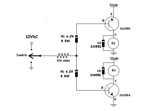
Relay R1 will switch on with a 12V input, and R2 will energize with a ground input.
When the input is left open, neither relay will be on.
Posted By: i am an idiot
Date Posted: May 03, 2009 at 8:51 PM
The Zener diodes are 1N5234B The other diodes pictured are 1N4001s
Posted By: dualsport
Date Posted: May 03, 2009 at 10:56 PM
You can put your two 470 ohm resistors in parallel to maintain the same current to make sure you drive the transistors into saturation. If your relays require a higher current you should decrease the resistor value to get more drive current.
Measure the Vce voltage across the transistor that's turned on to make sure it's driven fully on, should be close to zero volts.
Posted By: KPierson
Date Posted: May 04, 2009 at 9:57 AM
dualsport wrote:
You can put your two 470 ohm resistors in parallel to maintain the same current to make sure you drive the transistors into saturation. If your relays require a higher current you should decrease the resistor value to get more drive current.
Measure the Vce voltage across the transistor that's turned on to make sure it's driven fully on, should be close to zero volts.
You should be able to leave the resistor right at 470 as long as it is a 12vdc system. These transistors (from memory) have a gain of 35 so saturation really isn't an issue (theoretical output at 12vdc and 470 ohms is ~900mA). Can you explain how the top PNP transistor will be biased through the zener? I understand that the bottom zener will start conducting after the break down voltage is passed (6v in this case) but how is the top zener going to start conducting the (-) signal required to bias the PNP 3906? Also, if you have 12vdc feeding from the collector of the 3906 to the base won't it avalanch both diodes anyway? I'll have to add this to my list of circuits to build to see if it works out - I must say I'm skeptical at this point. ------------- Kevin Pierson
Posted By: dualsport
Date Posted: May 04, 2009 at 10:50 AM
It's the same thing with the top zener when the input being supplied is a ground signal. As long as the voltage across the zener is greater than the breakdown voltage, it'll start to conduct and pass current through. For the top zener, the voltage being applied is 12V in the standby condition, and then when the ground signal is applied, the anode of the diode tries to go to zero through the biasing resistor, so it'll conduct and maintain the 6.2V across it. Pretty much like ground switching a relay with the other side of the coil at 12V vs. switching it on by applying 12V to it with the other side of the coil grounded. Because the zener drops the voltage by about 6V, then you would need to use 6V as the driving source for calculating the bias resistor requirement. If the gain is 35, and the relay needs 200mA, then 6V would be ample for the base current. Since you already built up the original circuit it should be easy enough to try out. Give it a whirl and see- mouser has the diodes for pennies- :) If you have a very high supply voltage, you may want to use a higher zener voltage to prevent conduction in the standby condtion (basically the two zener voltages added up should be greater than the supply voltage)
Posted By: dualsport
Date Posted: May 06, 2009 at 9:21 AM
Are we giving up on this one?
A resistance added between the base and emitter of the transistors will help bias it to off in the standby mode, if you're finding that to be a problem.
Posted By: djfearny2
Date Posted: May 06, 2009 at 8:51 PM
I am waiting for the zener diodes to arrive.
and I am about to try the first circuit as described earlier in the thread/
-------------
Jon
Installer/Help Technician
---coral springs florida---
mecp certification is not always needed. I have it and it has not helped me out at all. my experience out shines it.
Posted By: djfearny2
Date Posted: May 06, 2009 at 9:55 PM
first setup with op chip failed
does not control relays. even with changing resistance.
-------------
Jon
Installer/Help Technician
---coral springs florida---
mecp certification is not always needed. I have it and it has not helped me out at all. my experience out shines it.
Posted By: djfearny2
Date Posted: May 06, 2009 at 9:57 PM
does any one know how to do a multiplex resited ground network??
-------------
Jon
Installer/Help Technician
---coral springs florida---
mecp certification is not always needed. I have it and it has not helped me out at all. my experience out shines it.
Posted By: i am an idiot
Date Posted: May 06, 2009 at 10:13 PM
Did you try the 2 relays and diodes on the first page of this thread?
Posted By: djfearny2
Date Posted: May 06, 2009 at 10:24 PM
yes i did and what happened was the resting ground would activate the other relay.
-------------
Jon
Installer/Help Technician
---coral springs florida---
mecp certification is not always needed. I have it and it has not helped me out at all. my experience out shines it.
Posted By: dualsport
Date Posted: May 06, 2009 at 10:32 PM
You need the zener diodes to provide an inactive zone where the relays are not energized.
If you want to drive the relays directly, you can simply put the zeners on the circuit as shown above, delete the 470k input resistor, and run the ends of the zeners to your relay coils. Make believe the transistors are relays, top one configured to ground switch, and the bottom one configured to high switch.
Your input signal has to provide enough current to drive the relays, and you have to make sure the relays are able to switch with 6V. If they don't, then you can just get 6V relays instead of the 12V.
That'd be the simplest if the circuits are looking too complicated.
Posted By: KPierson
Date Posted: May 06, 2009 at 11:05 PM
I built the op amp circuit and it worked! I built it exactly as shown with no added components. I also built the zener diode circuit and it worked as well. However, you have to be VERY careful when picking your zener diodes. I only had 5V zeners on hand so I used them. At 12vdc the output of the NPN would latch on and stay on until I activated the PNP. I slowly turned the voltage down and around 8.8vdc things started working as expected. So, I would assume that a 6v zener would only work at 10.5vdc or below. To get up to automotive range (14.8vdc) you would need around a 9v zener to work correctly. The low side of the input voltage with the 5v zeners was 6.5vdc. Below that the NPN wouldn't trigger. Thank you dualsport for not only posting the diagram but explaining how it works. I've learned quite a bit on this thread. Jon to answer you question about multiplexing you can use the op amps to set up a comparator circuit. You will need one op amp to be a low threshold and one to be a high threshold. You can run the outputs of both comparators through a NAND gate - if both inputs are off the gate will turn on to drive a transistor to drive a relay. I've done this before for a car and it worked, although it's far from elegent. A better solution would include an ADC and a microcontroller - far less parts count and much more flexibility. ------------- Kevin Pierson
Posted By: dualsport
Date Posted: May 06, 2009 at 11:53 PM
Yeah, the gain of the transistor driver will amplify any current that goes through the zener diodes, so the zener voltage has to be at *least* 1/2 of the supply voltage or more. The 5V x 2 you tried is less than the supply voltage, so they'll pass a large amount of current, same as if they were just shorted together and weren't there.
Any conduction at all through the zeners will be amplified by the transistors and drive the relay on.
Putting resistors between the base and emitters to bias it toward cutoff will also help make sure the transistors are turned off in standby.
All sorts of things to tweak it as needed, but that's basically the idea, the zener diode is like a blowoff valve that only opens up when there's enough pressure, and blocks any flow below the lower pressures. So putting them inline like that so that they both add up to a value greater than the supply voltage will act like an open circuit.
Then when the input is applied from the midpoint, a higher voltage than the breakdown is put across the diodes, and they open up to allow the current to flow. Then it allows the relay or transistor to be turned on.
You can try eliminating the transistors if the input signal can drive the relays directly. If your relays are sensitive enough to energize with 6V, it should work. You might give that a quick try since you have it built up already-
Posted By: dualsport
Date Posted: May 07, 2009 at 12:26 AM
KPierson wrote:
Out of curiosity, on this, when the input is left open and allowed to float, doesn't the output follow it and result in the relays turning on the same way it does in the direct transistor drive circuit?
I would have thought whatever voltage it floats to would end up turning on one or both of the relays? Even if it happened to float to exactly the midpoint and put 6V out, it would turn on both relays.
That's why I was wondering if there was supposed to be a condition where both relays are off and in standby.
Posted By: KPierson
Date Posted: May 07, 2009 at 5:27 AM
The problem with putting pull up/down resistors on the input is that if you do, you again lose your isolation (as you would have both a pull up and a pull down resistor going from battery to ground, which would give you exactly 1/2 your battery voltage in the standby condition on both outputs. One thing I did observe is that if the inputs of the op amp were disconnected the relays would turn on. Installing resistors would obviously fix this situation. However, when I connected both op amp inputs together both relays turned off and then the circuit operated as expected. I should have measured the output voltage in the standby condition but I didn't. ------------- Kevin Pierson
Posted By: djfearny2
Date Posted: May 07, 2009 at 9:10 AM
ok so here is my status
It is working basically.
I had the Transitors wired opposite so switched that, and now here is what im getting
1- have to diode isolate inputs.
2- negative output not strong enough to control a relay.
3- the possitive output is resting at possitive which is ok seeing as i can just wire the relay differently,.
now as far as the negative goes, it is strong enough to control the shifter without a relay which is better as I prefer not to here the relay clicking when shifting since i use the feature often. plus I have to diode isolate the output to the shifter as well or it disables the whole manual shifting.
However if i change the resistance value can that increase the output power if needed?
-------------
Jon
Installer/Help Technician
---coral springs florida---
mecp certification is not always needed. I have it and it has not helped me out at all. my experience out shines it.
Posted By: KPierson
Date Posted: May 07, 2009 at 10:38 AM
How did you end up wiring it? Make sure you are hooking the PNP and NPN up correctly - if you reverse the collector and emitter it won't work correctly. You shouldn't have to change any resistor values, the 470ohm should be more then enough to bias the transistor. djfearny2 wrote:
ok so here is my status
It is working basically.
I had the Transitors wired opposite so switched that, and now here is what im getting
1- have to diode isolate inputs.
2- negative output not strong enough to control a relay.
3- the possitive output is resting at possitive which is ok seeing as i can just wire the relay differently,.
now as far as the negative goes, it is strong enough to control the shifter without a relay which is better as I prefer not to here the relay clicking when shifting since i use the feature often. plus I have to diode isolate the output to the shifter as well or it disables the whole manual shifting.
However if i change the resistance value can that increase the output power if needed?
------------- Kevin Pierson
Posted By: djfearny2
Date Posted: May 07, 2009 at 11:38 AM
what will happen if i have the c and e reversed?
I am almost curtain i have them wired all correctly.
-------------
Jon
Installer/Help Technician
---coral springs florida---
mecp certification is not always needed. I have it and it has not helped me out at all. my experience out shines it.
Posted By: djfearny2
Date Posted: May 07, 2009 at 11:40 AM
I followed the diagram On the back of the radio shack packaging to determine c & E
-------------
Jon
Installer/Help Technician
---coral springs florida---
mecp certification is not always needed. I have it and it has not helped me out at all. my experience out shines it.
Posted By: djfearny2
Date Posted: May 07, 2009 at 11:40 AM
should both wires be resting at nothing or the opposite polarity of the output ?
-------------
Jon
Installer/Help Technician
---coral springs florida---
mecp certification is not always needed. I have it and it has not helped me out at all. my experience out shines it.
Posted By: KPierson
Date Posted: May 07, 2009 at 3:32 PM
How did you end up wiring it? There are several different schematics posted. When you asked about "both wires" resting what two wires are you talking about? If you are talking about the wires comming from the collectors of the transistors to the relays then the answer is yes. They will rest at nothing but the opposite polarity of the the output. This is because you are reading voltage through the coil of the relay. The actual transistor, with the relay disconnected, should rest at open. With the relay hooked up the collector should show whatever is on the other side of the coil. ------------- Kevin Pierson
Posted By: dualsport
Date Posted: May 08, 2009 at 8:25 PM
Here's a modification to Kevin's op amp circuit that should also work-
In this setup, the thresholds are set up by a resistor divider shown on the right, made up by three equal resistors. The values are not very important, they just need to be equal values. You don't want too low a resistance because that'll just waste power.
The threshold voltages at the taps are going to be 1/3 and 2/3 of the Vcc voltage, about 4V and 8V respectively.
The input is going to be sitting at 1/2 of the Vcc in the standby condition, when nothing is applied to the input, because of the resistor divider made up of the two resistors to the left.
So, in standby, op amp 2 is low, because the positive input is lower than the negative input threshold of 8V. Op amp 1 is high because the positive input is above the negative input threshold of 4V. This should drive both transistors off, and relays will be off.
Now if 12V is applied to the input, the positive input is greater than the 8V threshold on op amp 2, and it switches high. This turns on the relay on the bottom. Relay on the top controlled by op amp 1 remains off, because 12V is still above the 4V threshold.
Next, if ground is applied to the input, 0V is less than the threshold on op amp 2, so the relay on the bottom turns off.
OV is less than the 4V threshold on op amp 1, so now it goes low, and results in the upper transistor turning on, switching the upper relay on.
It could be rearranged if you want to use the same kind of transistors, but since you have both pnp and npn, you can just do it as shown.
If the drive output from the op amp is enough to serve your purposes, you could even move things around a bit and just use the outputs directly.
That should be enough ideas for you to finally skin this cat- 
|