any relay do this?
Printed From: the12volt.com
Forum Name: Relays
Forum Discription: Relay Diagrams, SPDT Relays, SPST Relays, DPDT Relays, Latching Relays, etc.
URL: https://www.the12volt.com/installbay/forum_posts.asp?tid=113479
Printed Date: April 18, 2026 at 10:56 AM
Topic: any relay do this?
Posted By: stupidpig
Subject: any relay do this?
Date Posted: April 28, 2009 at 11:12 PM
I want a relay (or combination of multiple relays / circuits) to do the following: Trigger +12vdc (X = Off, O = On):
XXXOOOOOOXOXOXXXXXXX
Output +12vdc (X = Off, O = On):
XXXXXXOOOOOOOOOOXXXX Basically I want output be switched on after the trigger be on for certain time (e.g. 3s), then the output only be turned off if the trigger is off for certain time (e.g. 3s). Any on/off change with 3s shouldn't affect the output. Can anyone help?
Replies:
Posted By: KPierson
Date Posted: April 29, 2009 at 6:08 AM
A combination of an on delay relay and an off delay relay should work.
-------------
Kevin Pierson
Posted By: i am an idiot
Date Posted: April 29, 2009 at 6:21 AM
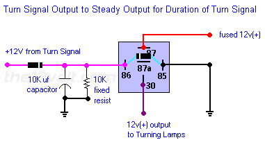
This relay setup will extend a pulse for a while. There is another diagram here somewhere that will delay the output for a time. A combination of the 2 should do what you want. However 3 seconds may be a stretch. It may take a transistor circuit on each relay setup to obtain the required 3 seconds. I know that someone can find the delay relay setup today, and I will lay out the transistors this evening. | Pulsed to Steady Output | If you have cornering lights and want them to come on only when your turn signal is on and you do not have a steady output, use the following for each side. This will give you a steady output while the turn signal is on. Increasing the size of the capacitor will give you a longer output if needed.
 |
Posted By: i am an idiot
Date Posted: April 29, 2009 at 6:23 AM
I spent a lot of time looking for that delay relay.
Posted By: stupidpig
Date Posted: April 29, 2009 at 1:36 PM
KPierson wrote:
A combination of an on delay relay and an off delay relay should work.
I was thinking about this too, but do you know where can I found the on delay and off delay relay? I search the web and can't found any.
Posted By: stupidpig
Date Posted: April 29, 2009 at 1:47 PM
i am an idiot wrote:
This relay setup will extend a pulse for a while. There is another diagram here somewhere that will delay the output for a time. A combination of the 2 should do what you want. However 3 seconds may be a stretch. It may take a transistor circuit on each relay setup to obtain the required 3 seconds. I know that someone can find the delay relay setup today, and I will lay out the transistors this evening.
Thanks. 3s just an example, I think anything more than 1.5s should work for my needs. My application for this is for power up the HID low beam. I want to trigger the low beam by the OEM low beam connector, which normally a simple relay harness should be ok, but the problem is my car will turn on both high beam and low beam when I try to flash the high beam, and I don't want the low beam HID to be fried in that 0.5s flash. I also don't want the HID keep switching on/off if there is any rapid power on/off change on the OEM low beam harness. I think I probably need three circuit put together: DelayOn - PulseToConstant - DelayOff
Posted By: stupidpig
Date Posted: April 29, 2009 at 4:23 PM
Oh, just relized that DelayOn/DelayOff probably not what I want. My understanding for DelayOn is turn on some time after one pulse, but what I want is to turn on only if the trigger is continuously on for certain time. Same for the DelayOff, what I want is turn off only when the trigger is continuously off for certain time.
Posted By: i am an idiot
Date Posted: April 29, 2009 at 7:30 PM
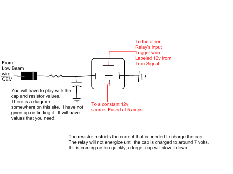
I thought that was exactly what you said in the beginning. That is exactly how it will work. Build the one that I posted earlier and use a larger capacitor to see how long it will stay engaged when the power is removed from the trigger wire. The above is the delayed off relay. The delay on circuit will trigger that one.
I still have had no luck finding the other diagram. Give me a minute, I will draw the diagram, you will have to play with the cap and resistor values.
Posted By: stupidpig
Date Posted: April 29, 2009 at 9:57 PM
I'm novice on circuit design, and I'm not sure the following will work or not.... 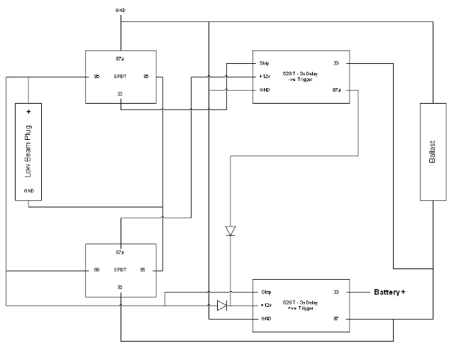
Posted By: stupidpig
Date Posted: April 30, 2009 at 1:32 AM
i am an idiot wrote:

Is it means the relay will only energized after a couple seconds (delay on), then when low beam off, the capacitor will discharge and energize the relay for a couple more seconds (delay off)? Wow, it is much simpler than what I comes up with.... What resistor and cap size should I start with, if I want aorund 3s delay?
Posted By: i am an idiot
Date Posted: April 30, 2009 at 4:02 AM
You will have to use the last picture in conjunction with the first picture I posted.
I know the Administrator knows where the diagram of the circuit is located on the site. He has retrieved it for me before. I keep hoping he reads this and knows where it is. Maybe he lost it.
The last picture will give you the delay on, and a slight delay off. The earlier pic will provide the delay off.
Try a 4700 Mic cap and a 220 ohm 1/2 watt resistor. I have no idea how much time this will take to energize. I can't add or subtract, much less do any strenuous math at this time of the morning. I will try to figure out some usable values for you today.
Posted By: i am an idiot
Date Posted: April 30, 2009 at 8:38 AM
If you have not purchased any capacitor yet and you can wait till Saturday or Sunday, this will be a much cheaper project if we use a transistor and a smaller cap and resistor combination. I will figure it out this weekend. The resistor and cap will feed the base of a transistor. It will then power the relay.
Posted By: stupidpig
Date Posted: April 30, 2009 at 12:42 PM
Thanks. I'm sure I can wait until weekend. BTW, did you have chance to look at the circuit I used 2x relay and 2x 528T? Just wonder will that work.... I know it is a whole lot more complex and expansive than what you have, but that may be useful if I want configurable delay, like 2s delay on and 60s delay off.
Posted By: i am an idiot
Date Posted: April 30, 2009 at 3:13 PM
I am not familiar with the DEI timers. I will look at your diagram tonight.
Posted By: stupidpig
Date Posted: April 30, 2009 at 5:33 PM
Thanks. I have a different question. What happen if I supply lower voltage, for example 7v, to a 12v coil SPDT relay? Will the 87 or 87a connected to 30 in this situation? Or both disconnected? Currently my car's high beam is used for both high beam and DRL (which I think it is running in lower voltage), I'm trying to turn on a different light for the DRL and keep the high beam bulb just for high beam.
Posted By: i am an idiot
Date Posted: April 30, 2009 at 6:34 PM
30 will be connected to one or the other except for the milliseconds of time that it takes to switch. It would have to be the most ideal situation for the relay to "Chatter" , or in your case the least ideal situation. I do not remember the actual voltage required to engage the relay, but I think it is near 7 volts.
Posted By: stupidpig
Date Posted: April 30, 2009 at 8:05 PM
Thanks. sounds like time to measure the actual voltage for the DRL. Hope that run much lower than 7v..... probably 5v.
Posted By: i am an idiot
Date Posted: April 30, 2009 at 9:16 PM
https://www.bcae1.com/temp/headlightdelay01.swf Transistor is a 2n6488 or equivalent. NTE 331 Increase the value of the 20 k to give you more delay on. Increase the delay off time. Save the file, I have no idea how long it will remain there.
Posted By: stupidpig
Date Posted: April 30, 2009 at 9:29 PM
i am an idiot wrote:
https://www.bcae1.com/temp/headlightdelay01.swf Transistor is a 2n6488 or equivalent. NTE 331 Increase the value of the 20 k to give you more delay on. Increase the delay off time. Save the file, I have no idea how long it will remain there.
Thanks alot. Will go to get the parts and try it. Increase the 20k to increase the delay on, but what will increase the delay off?
Posted By: i am an idiot
Date Posted: April 30, 2009 at 9:33 PM
Sorry, I have no idea what happened there. Increase the 1k to increase the delay off time.
It was a bit less than a second at 20K try a 47k and try 2.2k for the off delay.
Posted By: KPierson
Date Posted: April 30, 2009 at 9:40 PM
and don't forget the diode across the coil of the relay.
-------------
Kevin Pierson
Posted By: stupidpig
Date Posted: April 30, 2009 at 9:43 PM
1/2 watt for the 20k too? Also, which type of capacitor I should use? Electrolytic 12V? The only one 12V 100uF I found at Digikey is NLW100-12-ND, but it is not stocked.
Posted By: stupidpig
Date Posted: April 30, 2009 at 9:49 PM
Oh BTW, is there a limit on how big the two resistor I can use to get longer delay? I guess I can't just keep increasing those to get really long delay, like 60s, right?
Posted By: i am an idiot
Date Posted: April 30, 2009 at 9:56 PM
60 seconds will probably require a larger cap too. If you have problems with popping on your audio system when the relay disengages, then you may want to put the diode across the relay. The 2n6488 will not be damaged by the relay. The delay keeps it from collapsing fast and causing the spike.
Use at least a 16 volt cap I would feel much better if you used a 25 or 35 volt. If you are having to order all of this, order a 220 and a 330 mic also. You keep talking of more time. It sounds as though you may need the 220. You may be able to just use a 220 or 330 mic cap and leave the resistors as they are. A 1/4 watt should be fine for the 20K.
The transistor does not run hot at all. There is no need to sink it. However there is going to be 12 volts on the metal tab.
Posted By: stupidpig
Date Posted: May 01, 2009 at 1:31 AM
Sorry, I'm not very good in electronics, does "220 mic" means "220pF mica"? Can you take a look of the following list from Digikey and see whether they are correct? Thanks. | Index | Quantity | Part Number | Description | Customer Reference | Backorder Quantity | Unit Price
USD | Extended Price
USD |
|---|
| 1 | 5 | P10294-ND | CAP 100UF 35V ELECT FC RADIAL | | 0 | 0.38000 | $1.90 | | 2 | 2 | 338-1046-ND | CAP 220PF 500V MICA RADIAL | | 0 | 1.51000 | $3.02 | | 3 | 2 | 338-1045-ND | CAP 330PF 500V MICA RADIAL | | 0 | 2.06000 | $4.12 | | 4 | 2 | 2N6488GOS-ND | TRANS PWR NPN 15A 80V TO220AB | | 0 | 1.10000 | $2.20 | | 5 | 2 | PB681-ND | RELAY AUTO SPDT 30A 12VDC QC RES | | 0 | 2.93000 | $5.86 | | 6 | 10 | 47KH-ND | RES 47K OHM 1/2W 5% CARBON FILM | | 0 | 0.05800 | $0.58 | | 7 | 10 | 2.2KH-ND | RES 2.2K OHM 1/2W 5% CARBON FILM | | 0 | 0.05800 | $0.58 |
Posted By: i am an idiot
Date Posted: May 01, 2009 at 2:26 AM
Mic = MicroFarad. I do not know where the Mu or Mue symbol is on the keyboard. Notice above, the 100UF is a 100MicroFarad. The 220 and 330 are PF P is for PicoFarad. Also just so you know, an Axial lead capacitor means that there is a leg coming out of each end of the cap. A Radial lead cap has both legs coming out of the bottom of the capacitor. There is no right or wrong one, just depends on how you plan to build it. Radial is also known as PC (Printed Circuit).
Posted By: KPierson
Date Posted: May 01, 2009 at 5:19 AM
i am an idiot wrote:
60 seconds will probably require a larger cap too. If you have problems with popping on your audio system when the relay disengages, then you may want to put the diode across the relay. The 2n6488 will not be damaged by the relay. The delay keeps it from collapsing fast and causing the spike.
Use at least a 16 volt cap I would feel much better if you used a 25 or 35 volt. If you are having to order all of this, order a 220 and a 330 mic also. You keep talking of more time. It sounds as though you may need the 220. You may be able to just use a 220 or 330 mic cap and leave the resistors as they are. A 1/4 watt should be fine for the 20K.
The transistor does not run hot at all. There is no need to sink it. However there is going to be 12 volts on the metal tab.
Is there a specific reason you went with such a big transistor? I'm going to build this tonight but I will have to sub a transistor in place of the 2n6488. According to the datasheet the 2n6488 has an hfe of ~150 at 200mA so I'll try to find something with similar characteristics. ------------- Kevin Pierson
Posted By: stupidpig
Date Posted: May 01, 2009 at 5:23 AM
Thanks. Learn something new :) For the cap, the Axial version cost a lot more than the Radial one. Since I was planning to have the circuit (except the relay) on a PCB, I think Radial is ok. You said the transistor will not generate a lot of heat, but how about the resistor? As this is going to put under the hood, I'm planing to have the circuit sealed in a smal plastic box, butI'm not sure it will cause any heat problem or not.
Posted By: i am an idiot
Date Posted: May 01, 2009 at 11:30 AM
The only reason for the 6488 was that we have lots of them left over from the old punch 150 and punch 75 amps. And also, overengineering is always a good thing.. Figured the reduced size of the capacitors would allow the 6488 to fit somewhere. There is no heat issue at all.
Posted By: dualsport
Date Posted: May 04, 2009 at 10:53 PM
One possible consideration in switching the relay so slowly may be the high resistance of the relay contacts when the drive current is right at the threshold as it switches on and off.
If the relay has to carry a lot of current, it could be a problem with the contacts heating up. Ideally relays are switched on and off quickly for minimum contact resistance.
Some hysteresis in the drive circuitry or even just using the relay to drive a second relay might be a way to avoid this, if it proves to be any kind of issue. Using the first relay to drive a second one would basically allow the power relay to snap on and off fully. The first relay can be just a small relay since it only drives the coil of the power relay.
Posted By: stupidpig
Date Posted: May 08, 2009 at 2:59 AM
Parts finally arrived, and it works great . I tried 2.2K, 20K, and 220uF cap, which gave me about 5s delay-on and 4s delay-off. I'm still playing with different combinations to decrease a little bit on delay-on and increase a lot more on delay-off. My goal is to have about 3s delay on and more than 30s delay off (I guess the delay off part probably impossible). I do found one problem, which is if I keep turning the input on and off, it will still switch on the relay after a couple times. May be the cap keep adding charges and stored it.
Posted By: i am an idiot
Date Posted: May 08, 2009 at 6:04 AM
stupidpig wrote:
Thanks. 3s just an example, I think anything more than 1.5s should work for my needs.
Good thing we opted for the transistor.
Posted By: dualsport
Date Posted: May 08, 2009 at 7:54 AM
If you want to adjust the delay on time independently of the delay off time, just use a parallel combination of diode-resistor in series.
In place of the 20k resistor picture, put a resistor in series with a diode facing forward, and then in parallel with that, put a resistor with a diode facing backwards.
This allows each resistor to be adjusted to change one time without affecting the other.
Posted By: dualsport
Date Posted: May 08, 2009 at 8:02 AM
stupidpig wrote:
I do found one problem, which is if I keep turning the input on and off, it will still switch on the relay after a couple times. May be the cap keep adding charges and stored it.
That's perfectly normal, since the voltage isn't starting from zero if you don't allow it time to reset to the starting condition by charging or discharging the cap fully. You'd need a different circuit to have it reset immediately on a transition for a new timing cycle.
Posted By: stupidpig
Date Posted: May 08, 2009 at 2:19 PM
I tried a 330uF cap and replaced the 1K on picture with 20K, and it increased the delay-off to about 10s, not as much as I want but I think that's good enough. The problem with the 330uF is it increased the delay-on also. I think by decreasing the 20K on picture should shorten the delay-on. Time to get a couple resistor with different ohm for try... Oh, any suggestion on how to drain the cap if I just pulse the input? A relay to ground the cap when input is off sounds overkill.
Posted By: stupidpig
Date Posted: May 09, 2009 at 12:59 AM
OK, here is what I used finally. 1K in picture replaced by 47K, 20K in picture replaced by 15K, and 330uF cap. About 5s delay-on and 17s delay-off. Originally I want to use 10K instead of 15K, which give me 3s delay-on and 16s delay-off, but the relay will switched on after I pulse the input for 4 times only. With the 15K, the relay only switched on after pulse the input for 12 times, sounds acceptable. Thanks for all the help :)
Posted By: stupidpig
Date Posted: June 05, 2009 at 4:21 AM
Unfortunately, this thing die after 3 days. I checked the spec for 2n6488, and found that the max emitter-base voltage is 5v, and we are following 12v to the base to turn it on. Will that be the cause of the death?
Posted By: i am an idiot
Date Posted: June 05, 2009 at 4:34 PM
Have you checked to make sure the transistor is the defective device?
Posted By: stupidpig
Date Posted: June 05, 2009 at 7:07 PM
Nope, but will try once I back to home.
Posted By: i am an idiot
Date Posted: June 05, 2009 at 7:27 PM
I didn't go back and read what you wound up using for the capacitor values. What about the 20K resistor, did you change that to a different value?
Posted By: stupidpig
Date Posted: June 05, 2009 at 7:56 PM
1K become 47K, 20K become 15K, and cap is 330uF. It work great for the first few days, but then one night I'm leaving office late (around 1am), and then I just found out I can't turn on the low beam anymore. Then I just drive 50 miles back to home with the high beam, and luckily no one flash me and no cop around. Then the low beam work again when I removed the circuit after I back to home.
Posted By: dualsport
Date Posted: June 06, 2009 at 8:16 PM
The base-emitter voltage of 5V isn't the problem, it doesn't see more than 0.7V there.
Depending on the relay being used, it could dissipate over 500mW in the transistor as it slowly transitions between off and on. It's going to peak out right at the middle when the relay gets half of the 13.5V and the transistor gets the other half.
A standard automotive type relay coil resistance of 88 ohms results in a peak of 0.518W at a 13.5V supply voltage. The slow transition is forcing the transistor to remain in the active region for a long time instead of acting as a switch. A transistor driven on hard and fast to saturation will dissipate very little power, but it's not doing that in this circuit.
If the relay is a lower power relay it'd be less of a problem, but even so, it's going to dissipate some heat and it has to go somewhere.
It may not sound like much to a transistor rated for 75W, but that figure always assumes that it's properly heatsinked to get rid of the heat. The transistor should be mounted properly here.
Try touching it as it operates to see how hot it's getting.
Also might see if the relay contacts may have degraded from the slow switching, it's harder on them when high current has to pass through them without the contacts getting full pressure. Higher contact resistance means the contacts heat up more during the transition period.
Posted By: i am an idiot
Date Posted: June 06, 2009 at 10:02 PM
I have used that transistor to trigger a relay many times. They do not heat up at all even keeping it energized for hours. However I did not try switching this setup many times to see if that would heat it up. I see no reason for it to have failed. I am hoping he has a failed connection somewhere. I guess we have to wait and see what he finds.
Posted By: dualsport
Date Posted: June 06, 2009 at 10:47 PM
It's fine when it's either on or off, the only time it starts to dissipate any heat is during the switching period.
The original circuit pictured has a relatively short delay time, so it doesn't linger in that middle area for long.
When the circuit was changed to get the long delay times is where it might start to be an issue. If he didn't repeatedly switch it on and off, it should be okay, since it would have a chance to cool back down. It'd take a while for it to heat up to the point where it might be a problem, since it's such a big transistor.
Looking back at why he needed to do this, it's probably not any problems from the transistor heating up, since it's to power HID headlights. I don't think he'd be turning it on and off repeatedly while driving along. I'd guess it's more likely to be a relay contact failure because HIDs have a high surge current on startup, and the slow relay switching might result in the contacts burning up. Or maybe just a wire connection came loose like you said.
Posted By: stupidpig
Date Posted: June 07, 2009 at 4:30 PM
If heat is going to be a problem, then it probably failed because of that. I sealed the whole circuit with some eproxy (not the themal transfer one though), as I thought I read there is not going to be any heat issue. It going to take me awhile to remove the eproxy and get the transistor out and test it.
Posted By: i am an idiot
Date Posted: June 07, 2009 at 4:56 PM
When I said heat was not going to be an issue, what I meant was it did not need a heat sink. I did not realize you were going to dip the board in epoxy.
Posted By: stupidpig
Date Posted: June 07, 2009 at 7:52 PM
haha, yup, that's my fault :) Well, I can't really test it since when I try to remove the epoxy, I removing too much with the dremel and damaged the transistor. Anyway, I'm going to build another one, and this time I will make sure I'm using the thermal conductive epoxy instead. :)
Posted By: i am an idiot
Date Posted: June 07, 2009 at 7:55 PM
I would make sure it works for a week or so before I coated it. Put it in a project box and maybe inside of a plastic bag for a week or two to make sure it is going to hold up.
Posted By: dualsport
Date Posted: June 07, 2009 at 8:31 PM
You could still see if the transistor is working without digging it out of the epoxy, if you can hear the relay click at all, it should still be working okay. You might try to check the relay and connections then.
Posted By: i am an idiot
Date Posted: June 07, 2009 at 8:48 PM
He already ran a dremel tool through the case of the transistor.
|