relay diagram planning advice needed
Printed From: the12volt.com
Forum Name: Relays
Forum Discription: Relay Diagrams, SPDT Relays, SPST Relays, DPDT Relays, Latching Relays, etc.
URL: https://www.the12volt.com/installbay/forum_posts.asp?tid=114409
Printed Date: May 14, 2026 at 4:04 AM
Topic: relay diagram planning advice needed
Posted By: defnu
Subject: relay diagram planning advice needed
Date Posted: June 12, 2009 at 12:41 PM
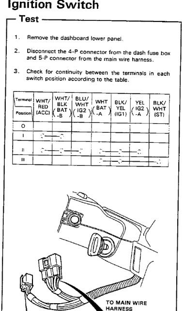
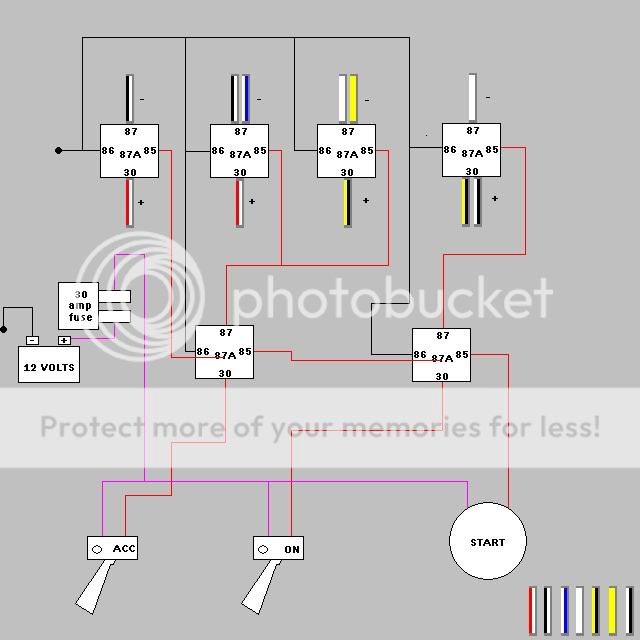
hello. i'm working on removing key cylinders for my doors (completed) and ignition. i already have a keyless entry alarm system that i had to learn to install myself. my end goal is to learn about wiring basics and relays are where i'm at right now. i wired the relays to my door locks but i guess that's not enough relay work for me to remember by heart. ANYWAYS! below is a diagram of my ignition system. i have a diagram for the starter button (does not incorporate a connection with WHT (BAT -a). i am left with wiring the ACCssories (I) and the ON (II) switch to a three option toggle (off, option a, option b) how can i acheive this with the least amount of relays? thanks for any input. [IMG]https://i272.photobucket.com/albums/jj173/defnu/IGN.jpg[/IMG] ------------- hello.
Replies:
Posted By: defnu
Date Posted: June 12, 2009 at 1:04 PM
------------- hello.
Posted By: defnu
Date Posted: June 12, 2009 at 1:05 PM
sorry for my noob posts, but if you have an idea just label the wires A-G
-------------
hello.
Posted By: KPierson
Date Posted: June 12, 2009 at 1:26 PM
You should be able to do it with 5 relays (one relay for each switched wire) and 9 diodes. The diodes will prevent backfeeding from position to position. relay coil A = WHITE/ black
relay coil B = WHITE/ blue
relay coil C = BLACK / YELLOW
relay coil D = yellow
relay coil E = BLACK/ white So - Switch Output 1 --> Diode --> relay coil A Switch Output 2 --> Diode --> relay coil A
Switch Output 2 --> Diode --> relay coil B
Switch Output 2 --> Diode --> relay coil C
Switch Output 2 --> Diode --> relay coil D
Switch Output 2 --> Diode --> relay coil B Switch Output 3 --> Diode --> relay coil C
Switch Output 3 --> Diode --> relay coil E Then you would just need to make sure the correct output is wired to the correct battery source. ------------- Kevin Pierson
Posted By: defnu
Date Posted: June 12, 2009 at 2:06 PM
KPierson wrote:
You should be able to do it with 5 relays (one relay for each switched wire) and 9 diodes. The diodes will prevent backfeeding from position to position. relay coil A = WHITE/ black
relay coil B = WHITE/ blue
relay coil C = BLACK / YELLOW
relay coil D = yellow
relay coil E = BLACK/ white So - Switch Output 1 --> Diode --> relay coil A Switch Output 2 --> Diode --> relay coil A
Switch Output 2 --> Diode --> relay coil B
Switch Output 2 --> Diode --> relay coil C
Switch Output 2 --> Diode --> relay coil D
Switch Output 2 --> Diode --> relay coil B Switch Output 3 --> Diode --> relay coil C
Switch Output 3 --> Diode --> relay coil E Then you would just need to make sure the correct output is wired to the correct battery source.
nice, thanks! i've never worked with diodes but i'm going to look that up. is there some kind of rating i should look for? i'll be reading up regardless, thanks much again! ------------- hello.
Posted By: KPierson
Date Posted: June 12, 2009 at 4:54 PM
1A diodes will be adequate for your application
-------------
Kevin Pierson
Posted By: howie ll
Date Posted: June 13, 2009 at 2:05 AM
Anyone thought about (possible) factory transponder, steering lock etc etc etc. Fun, possibly expensive, lots of extra wiring etc. etc.
Posted By: defnu
Date Posted: June 13, 2009 at 2:44 PM
hopefully this will work. thanks for the conformation. i'm also in the market for a single toggle switch that can handle both "ACC" and "ON." i'm just not sure what the tabs for wire mounting would look like. would this switch be called a dpdt? also, what websites are good for relays and switches? i'm in elk grove california and there is not anything local with a reasonable price. the only thing radioshack had in stock were spst relays for $7.00 plus tax (CAlifornia) a piece!? i remember getting them for less than $5 from autozone and those came with pigtail harness' for the relay AND were spdt! ------------- hello.
Posted By: defnu
Date Posted: June 13, 2009 at 2:49 PM
also, i don't know where to place the 1amp diodes  ------------- hello.
Posted By: defnu
Date Posted: June 13, 2009 at 2:50 PM
lol, i also don't know if thats the correct way to place the fuse or the correct fuse....im such a noob! i did try my best to write out a clean diagram though. ------------- hello.
Posted By: howie ll
Date Posted: June 13, 2009 at 4:41 PM
Yes but 30amp fuse for EACH RELAY , i.e. ACC, IGN and START. The diodes are placed across 85 and 86 with the bands towards 85 the way you are wiring this, you've actually reversed the convention, 85 should be the ground side of the coil but it don't matter in practice as long as you consistantly do the same thing. Try getting hold of an old Mini flick lighting switch for your needs, first pos gives you ACC, second ACC and IGN at the same time. What car is this going in to?
Posted By: defnu
Date Posted: June 13, 2009 at 5:15 PM
yeah, i'm having trouble finding a single switch that does this for me. here's a link to my build thread https://www.honda-tech.com/showthread.php?t=2261397. ignore the dates, lol. our economy is effecting me hard too! lol. the car is a 1988 honda crx (ef7) thanks for the diode and relay information. ------------- hello.
Posted By: howie ll
Date Posted: June 14, 2009 at 3:42 AM
OK, so no transponders to worry about, now you've got to get rid of the steering lock. Got any vehicle dismantlers near you (wreckers yards, whatever you call them in the US)? Do some removals from the fuse boxes!
Posted By: howie ll
Date Posted: June 14, 2009 at 4:10 AM
That circuit is wrong, sorry I'm baby sitting my 9 and 11 year old grandchildren and I haven't had time to look properly. Your white black and white battery feeds should be fused somewhere, either at the battery or the engine bay fusebox adjacent to the engine bay rear bulkhead. These factory fuses should be at least 30 amps each. Now this:- Ground to first combi switch, first position, thin black cable to 85 and WHITE/ black from battery to 86 and 30, output to WHITE/ red from 87. Second position, thin black to 85 on three relays, white batt to 86 and 30 and ouputs (87) to BLACK / YELLOW, blue /white and yellow. Starter button thin black to ground, output to another relay, 85 again, battery white to 86 and 30, BLACK/ white starter output from 87. This will put much less current on your switches. Now here's the important part:- Before you start, some of these circuits e.g. ACC, and blue/white , will power down during the start (AKA cranking) cycle. Check. You will need a small 3 or 4 (you will probably only get a 4 pole) relay or 3 small case low currrent (under 5 amps). Output from starter switch to relay(s) 85, white ignition to 86, those thin blacks to the acc and 2 ignitions, NOT BLACK/ yellow or yellow in to 30 and out to 87. This will dump them during the start cycle. VERY IMPORTANT. Diodes please across every relay, between 85 and 86 diode bands towards 86.
Posted By: defnu
Date Posted: June 16, 2009 at 6:45 PM
sorry for such a late response to my own thread, i will be reading this after this post just to let any readers know this is still a live thread.
-------------
hello.
Posted By: defnu
Date Posted: June 16, 2009 at 6:47 PM
defnu] wrote:
p>
*quoting for same page reference ------------- hello.
Posted By: defnu
Date Posted: June 16, 2009 at 6:50 PM
defnu] wrote:
p>hopefully this will work. thanks for the conformation. i'm also in the market for a single toggle switch that can handle both "ACC" and "ON." i'm just not sure what the tabs for wire mounting would look like. would this switch be called a dpdt? also, what websites are good for relays and switches? i'm in elk grove california and there is not anything local with a reasonable price. the only thing radioshack had in stock were spst relays for $7.00 plus tax (CAlifornia) a piece!? i remember getting them for less than $5 from autozone and those came with pigtail harness' for the relay AND were spdt!
*quoting for same page reference ------------- hello.
Posted By: defnu
Date Posted: June 16, 2009 at 7:21 PM
so this circuit would not work if i want the previous switches to shut off when the starter button is pushed down? i wanted to replicate the oem action with the ignition switch using the two toggle switches and a single push start switch. so far, what i'm reading from your reply is to reverse my grounds on the relays to 85 and place the diodes on each relay? all of the wires i'm working with already has an oem location for the fuses. ------------- hello.
Posted By: defnu
Date Posted: June 17, 2009 at 11:42 PM
if someone can draw it up the right way for me, i'll paypal them $10.00. thanks again.
-------------
hello.
Posted By: dualsport
Date Posted: June 18, 2009 at 8:28 AM
You might not want to permanently connect the WHT/BLK and BLU/WHT wires as you show in your diagram. Without having them separated by relays, you can't open them up as required for the OFF position.
You can run set it up so that the upper left relay connects the WHT/BLK to WHT/RED in ACC or ON position, and the next relay connects WHT/BLK to BLU/WHT when in ON position. (Don't connect WHT/BLK and BLU/WHT as you were planning)
Use diodes to isolate the feeds into the relay controls so they energize only when needed:
RELAY #1 would be connected to the ACC control, and #2 connected to the ON switch control, but add a diode between the two relay coil inputs with the stripe towards relay #1, so that the ON control will turn on both relays, but the ACC control will only turn on the first relay, with the diode blocking the second one from coming on.
You can work out something similar for the other connections.
Posted By: defnu
Date Posted: June 19, 2009 at 10:09 AM
hmm....ok. i'm going to draw up another diagram. thanks again guys. i'm still willing to pay $10 bucks for a working diagram.
-------------
hello.
Posted By: defnu
Date Posted: June 19, 2009 at 11:57 AM
dualsport wrote:
You might not want to permanently connect the WHT/BLK and BLU/WHT wires as you show in your diagram. Without having them separated by relays, you can't open them up as required for the OFF position.
You can run set it up so that the upper left relay connects the WHT/BLK to WHT/RED in ACC or ON position, and the next relay connects WHT/BLK to BLU/WHT when in ON position. (Don't connect WHT/BLK and BLU/WHT as you were planning)
Use diodes to isolate the feeds into the relay controls so they energize only when needed:
RELAY #1 would be connected to the ACC control, and #2 connected to the ON switch control, but add a diode between the two relay coil inputs with the stripe towards relay #1, so that the ON control will turn on both relays, but the ACC control will only turn on the first relay, with the diode blocking the second one from coming on.
You can work out something similar for the other connections.
so the way you're explaining it makes sense....i would have to add one more relay though right? for the yellow wire? regardless, i'll be working on another diagram to correct all my other mistakes. ------------- hello.
Posted By: dualsport
Date Posted: June 19, 2009 at 5:21 PM
For what I was describing, you don't need another relay, you're just controlling the relays differently. Think of the WHT/BLK as the common for the two relays, and the other two wires being connected to it through the two relays. The relays just need to be controlled so they only come on when needed, not always together.
|