constant to momentary
Printed From: the12volt.com
Forum Name: Relays
Forum Discription: Relay Diagrams, SPDT Relays, SPST Relays, DPDT Relays, Latching Relays, etc.
URL: https://www.the12volt.com/installbay/forum_posts.asp?tid=115326
Printed Date: May 05, 2026 at 11:18 PM
Topic: constant to momentary
Posted By: yonubear
Subject: constant to momentary
Date Posted: July 27, 2009 at 8:17 PM
witht he constant to momentary relay diagram when the relay turns off will the output wire become a ground i would assume so but I figured I would ask before i tryed it
Replies:
Posted By: yonubear
Date Posted: July 28, 2009 at 12:59 PM
hey I need a bit of help guys i buildt the relay as shown however it doesn't turn off i left it hooked up for a good 10min and it stays on any advice would be great
Posted By: the12volt
Date Posted: July 28, 2009 at 1:21 PM
No, the relay does not supply ground on terminal 30 (output wire). Are you using a polarized capacitor? If so, what size? 
-------------  the12volt Support the12volt.com the12volt Support the12volt.com
Posted By: yonubear
Date Posted: July 28, 2009 at 1:28 PM
yes it is a polarized cap it is 1000uf 35vdc
Posted By: the12volt
Date Posted: July 28, 2009 at 2:50 PM
Please double check all of your connections. 30 is the output wire that provides a momentary 12V+ immediately after terminal 86 is connected to 12V+ through a switch (Accessory, Ignition, etc.). Terminal 87 goes to a constant 12V+ source (battery). Terminal 85 is connected to a polarized capacitor and resistor wired in parallel that are each connected to ground as shown in my diagram. Terminal 87a is not used. Pay close attention to the diode across the coil. The cathode side (with stripe) is toward 86. The anode side is toward 85. If necessary, bench check it before installing it in the vehicle. I've used this configuration many times and have never had an issue with it. ------------- the12volt Support the12volt.com
Posted By: flybyu
Date Posted: December 11, 2009 at 1:42 AM
the12volt wrote:
Please double check all of your connections. 30 is the output wire that provides a momentary 12V+ immediately after terminal 86 is connected to 12V+ through a switch (Accessory, Ignition, etc.). Terminal 87 goes to a constant 12V+ source (battery). Terminal 85 is connected to a polarized capacitor and resistor wired in parallel that are each connected to ground as shown in my diagram. Terminal 87a is not used. Pay close attention to the diode across the coil. The cathode side (with stripe) is toward 86. The anode side is toward 85. If necessary, bench check it before installing it in the vehicle. I've used this configuration many times and have never had an issue with it.
I'd like to go from a constant 12 volt input and as it loses 12 volts it pulses 12 volts to the other side . Is it possiblle?
Posted By: i am an idiot
Date Posted: December 11, 2009 at 6:30 AM
flybyu wrote:
I'd like to go from a constant 12 volt input and as it loses 12 volts it pulses 12 volts to the other side . Is it possiblle?
Are you needing a 12volt pulse when the relay de-energizes? If so, it will take 2 relays, but I am sure we can figure it out for you. It would help if we knew your exact application.
Posted By: lucatz
Date Posted: January 21, 2010 at 10:12 PM
Hi, New forum member looking for some help. My application requires a 12 volt pulse of 1/2 seconds 50mA. The tricky part is that I need this pulse when the contstant 12v is applied and also when it is removed. Any help appreciated Luca
Posted By: i am an idiot
Date Posted: January 21, 2010 at 11:40 PM
I have a diagram that I think will work for you. I have not built and tested it yet. It may take a 2200 mic capacitor. You will have to build it and test it. My thinking is that when the left relay is turned on, it will energize the right relay until the capacitor charges, then the right relay will disengage, that will be the piulse when the wire goes positive. When the wire goes dead, the left relay will now place ground on terminal 86 of the right relay. The cap wil be charged, thus powering the right relay briefly. This will be your pulse when the wire goes dead. In case you missed it earlier, I have not built and tested the above Idea. You will have to test it before attempting to install it in a vehicle. You can ditch the resistor, it will not be needed. Test it and let me know if it works. Changing the cap size will change the llength of the pulse. 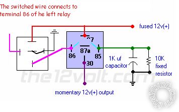
Posted By: lucatz
Date Posted: January 22, 2010 at 7:26 AM
Thanks I am an idiot, I will get the parts today and substitute the 1000uF cap for a 2200uF cap and also remove the resistor. Just to let you know the application is for home theater use. I have a Classe CA-150 that requires a 12 pulse to turn it on and a 12 volt pulse to turn it off remotely. Most components only supply 12v constant nowadays, so this is why I am looking for a solution. Thanks for your help Luca
Posted By: i am an idiot
Date Posted: January 22, 2010 at 8:57 AM
It may be ok with the 1000 mic capacitor. A larger cap will yield a longer pulse. I am concerved about the length of the pulse when power is removed from circuit.
Posted By: lucatz
Date Posted: January 23, 2010 at 10:05 PM
It works exactly like you said. Hard to tell the both pulses seem the same to me. Thanks a million. Luca
Posted By: aarong81
Date Posted: February 18, 2010 at 6:03 PM
Hello, Im new to this forum and I need to make a constant to momentary relay but would like to get a diagram or at least a parts list of what I need in place of the ones in the diagram above for my specific application. What I need it to do.... I have a terrarium with tree frogs and they are from a rainforest and need lots of humidity. I have an electric water mister that runs on 3v (2 AA), but I will replace the batteries with a 3v power adapter. I need this sprayer to turn on for aprox 4-5 seconds and stay off for a couple hours. I already have the means to cycle the several hours part via an outlet timer and that will operate the constant to momentary relay which will hopefully give 4-5 sec of 3v power to the mister. I think I need a different capacitor than shown, what size will I need for 4-5 seconds of 'ON' operation? Will this relay STAY off after this initial ON cycle? My outlet timer is only capable of providing 30min intervals of on and off and I only want 4-5sec of spray. One more question, Aside from using the required 12v supply to operate the relay....Can I use 3v fused through the relay instead of 12v shown in the diagram? I dont think thats a problem but Im not sure and wondered why it specifies 12v fused if not all applications use 12v. Thank you for your time, ------------- Aaron Griffin
Posted By: i am an idiot
Date Posted: February 18, 2010 at 7:10 PM
You will have to try this with a 10,000 microfarad capacitor. How long does your timer keep the power off? Every time the timer turns on, it should have output for near 5 seconds. As long as the off time is at least a minute, it should reset just fine and be ready for the next cycle. Yes you can run 3 volts through the contacts of the relay. 30 and 87.
| Constant to Momentary Output () |
The capacitor allows the coil of the relay to be energized until the capacitor stores a charge, thus de-energizing the coil. The resistor bleeds off the charge of the capacitor when positive voltage is removed from the other side of the coil. You can increase the output time by simply changing the value of the capacitor. This one will give you about a 1/2 second output.
|
Posted By: aarong81
Date Posted: February 18, 2010 at 10:04 PM
Thank you for the fast reply. My timer will cycle on for 30 minutes then cycle off for the next 3 or 4 hours. Its one of those wall outlet timers that has a round dial that has pegs in it each indicating 30 minutes of time and you either press them in or pull them out for on or off. Out of curiousity, After the relay is used for 4 or 5 seconds, Will the relay still be drawing 12v current? It seems that the 12v current is fed into the capacitor the entire time you send current to 86. If thats the case, how much current is the fully charged capacitor drawing? Is there a risk of overheating the capacitor? The shortest ammount of time I can send power to 86 is 30 minutes and I will be using a 12v power adapter between 500ma to 1amp. Is this too much or not enough? Thanks again. ------------- Aaron Griffin
Posted By: i am an idiot
Date Posted: February 19, 2010 at 7:59 AM
The cap will be fine being energized for however long. There will be minimal current draw. I mean minimal. Very Minimal. You can leave it on for days and not have any problems. The reisistor is bleeding the voltage from the capacitor. The only current through the circuit is keeping the cap charged. If you are worried about current draw, change the resistor to a 1 MegOhm resistor. It should drain the cap in the 30 minutes. Then there will be less current draw to keep the cap charged. Either way will be very minimal current.
Posted By: aarong81
Date Posted: February 19, 2010 at 4:22 PM
I went shopping for the parts I needed today and put it together. I could not find a single capacitor over 3500 uF or so. Instead I bought a capacitor kit with several sizes upto to 3500 uF and I used 6 different ones to total around 7400 uF I think. This makes the relay stay closed for about 10 seconds! Could this longer than expected time be due to using a "light duty", low coil draw, pc relay? I may cut one off if I decide 10 sec is too long. I put the capacitors in parallel, not in series. I wasnt sure which was correct but it seems to work fine like this. I wasnt even sure if cobbling a bunch of random caps together would even work. I took pics of the project if your curious how it looks. This is actually my first electronic build from scratch I guess, I never built anything on a blank electronic board before. I have one main concern yet. When I energize the board and the relay does what it should, it takes at least 30 minutes or more to drain the caps down before resetting. This really isnt a problem in the real world use of this relay since it will only need to power up maybe 3 times a day, but for testing it I cannot power it up more than once an hour or so. I have several extra 10k, 1/2 watt resisters. Can I add 1 more resister to drain the caps in half the time or will that be more detremental in the long term use? Again, its only desired for 'seeing' it work sooner while testing. Heres the pics. BTW, in the pics you will notice I have 2 diff power adapter jacks. 1 is for powering the relay, the other is the power supply for the water mister. Also you will see 2 wires attached to the board, these go to the water mister. There was probably a better way to wire it up but I am pretty noob at it. Thanks so much for helping me! https://i49.tinypic.com/20sd192.jpg https://i49.tinypic.com/2gv66qg.jpg https://i48.tinypic.com/2yknyc3.jpg https://i45.tinypic.com/2gx0h1s.jpg https://i45.tinypic.com/33xkbk5.jpg ------------- Aaron Griffin
Posted By: aarong81
Date Posted: February 19, 2010 at 7:36 PM
After testing it again I was unable to get the relay to actuate and close. So I added another resistor next to the first one in parallel and after an hour or so it still wont reset. I did some research and found one source that says 'increasing the resistor size increases the recovery time or discharge time of the capacitors'. Is this true? If I want the recovery time shortened, I need a smaller resistor? Im so confused about the part the resistor plays and how it works that I must ask...... What would be considered "smaller"? I have 10k Ohm resistors now. Is 5k Ohm smaller? Or does less Ohms mean larger resistor? As it is, Im sure it wont reset soon enough because when I test it I plug the power source into the relay for only a couple seconds and it still takes forever to reset. In the real world scenario it will be powered up for 30 minutes before disconnecting power, so I need it to reset alot faster. My setup so far.... Same as diagram except I am using 7440 uF cap. And I recently added a 2nd resistor < color=#2200cc>parallel with the first one. If I need a weaker resistor, can I use 2 of my 10k resistors in series, effectively making a 20k resistor? I believe what I did was make 5k Ohm resistor. Can you clear up my confusion? Thanks alot.
-------------
Aaron Griffin
Posted By: i am an idiot
Date Posted: February 19, 2010 at 8:43 PM
The resistance of the relay coil does make a difference with the calculations. A Bosch/Now Tyco relay draws 160 milliamps of current. The cap has to charge through the relay coil. Higher resistance coil = takes longer to charge the cap. Remove some capacitance untill you get your desired time.
Posted By: i am an idiot
Date Posted: February 19, 2010 at 8:58 PM
Yes if you place 2 10K resistors in series it will yield 20K Paralleled will yield 5K
Posted By: aarong81
Date Posted: February 19, 2010 at 9:10 PM
Ok, that part makes sense about the resistors in series or parallel. But I need to know which way do I need to go to shorten the recovery time? I have 2 10k resistors parallel now, but each time I try to test it again, it hasnt reset yet and I just recharge the caps everytime. I even tried shorting the caps across for a minute figuring it would drain them right away and it still doesnt reset it. Is that normal? ------------- Aaron Griffin
Posted By: i am an idiot
Date Posted: February 19, 2010 at 9:14 PM
I thought you had a minimum of 30 minutes down time? If you just need to discharge the caps for testing the duration of the output, you can discharge the caps with a piece of wire.
Posted By: aarong81
Date Posted: February 19, 2010 at 10:46 PM
While sending power to the relay board, I wiggled the components and found that the diode had a loose soldier. Re-soldiering the diode, the relay works like it had at first. Now I am letting it set unpowered to see if 30 minutes will be enough time to reset the caps. Just prior to finding the loose connection, I also removed the 2nd resistor. So I will get a good base reset time with the single resistor and hopefully wont need the other. But to confirm, will a 5k resistor reset the cap faster than a 10k resistor? Thanks for being patiant, Im learning. ------------- Aaron Griffin
Posted By: i am an idiot
Date Posted: February 19, 2010 at 10:49 PM
Yes the 5K will reset the cap twice as fast as a 10K.
|