current requirements
Printed From: the12volt.com
Forum Name: Relays
Forum Discription: Relay Diagrams, SPDT Relays, SPST Relays, DPDT Relays, Latching Relays, etc.
URL: https://www.the12volt.com/installbay/forum_posts.asp?tid=115909
Printed Date: November 28, 2025 at 11:32 AM
Topic: current requirements
Posted By: bowez
Subject: current requirements
Date Posted: August 25, 2009 at 7:24 PM
Looking at building a circuit that will use a RC timer to drive the coil and wondering if the resister requirement (~4M ohms)is going to effect the coil operating?
Replies:
Posted By: i am an idiot
Date Posted: August 25, 2009 at 9:04 PM
We need way more information. Way more. ------------- Let's Go Brandon Brown. Congratulations on your first Xfinity Series Win. LGBFJB
Posted By: bowez
Date Posted: August 25, 2009 at 9:44 PM
Well I haven't picked specific the relays yet, but do know will need a contact Amp requirement of 5A, and SPST for pertinent relays.
What other info is needed? I don't plan/want to use 30Amp automotive relays for they are too pricey and way over kill.
1micro F is the Cap size.
Both Cap and Resistor are not set in stone but just working numbers for now, (using these size because are locally available).
Posted By: i am an idiot
Date Posted: August 25, 2009 at 9:57 PM
How are you planning to connect the relay to the 4 meg resistor and the 1 mic cap? What is it you are trying to do with the relays?
-------------
Let's Go Brandon Brown. Congratulations on your first Xfinity Series Win. LGBFJB
Posted By: bowez
Date Posted: August 26, 2009 at 6:12 PM
Either solder or on a bread board, the resistor and Cap will be in parallel before the coil.
Trying to make a timed relay. One will be time delayed and another time limited.
Posted By: i am an idiot
Date Posted: August 26, 2009 at 9:06 PM
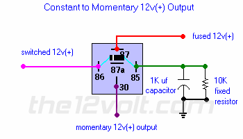
This is a constant to momentary setup. If you have a signal wire that goes positive for a while and you only want that wire to control a relay briefly, this is what you want.  Constant to Momentary Output () Constant to Momentary Output () | The capacitor allows the coil of the relay to be energized until the capacitor stores a charge, thus de-energizing the coil. The resistor bleeds off the charge of the capacitor when positive voltage is removed from the other side of the coil. You can increase the output time by simply changing the value of the capacitor. This one will give you about a 1/2 second output.
 |
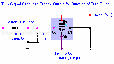
The following diagram will take a short pulse and make it longer.  Pulsed to Steady Output () Pulsed to Steady Output () | If you have cornering lights and want them to come on only when your turn signal is on and you do not have a steady output, use the following for each side. This will give you a steady output while the turn signal is on. Increasing the size of the capacitor will give you a longer output if needed.
 |
------------- Let's Go Brandon Brown. Congratulations on your first Xfinity Series Win. LGBFJB
Posted By: bowez
Date Posted: August 27, 2009 at 5:34 PM
Not to be an arse but not the scope of my question.
I was wondering if 4M ohms is going to limit current to much to drive a coil let alone two.
Posted By: i am an idiot
Date Posted: August 27, 2009 at 5:55 PM
That depends on the resistance of the coil. But I can not see a 4 meg resistor allowing enough current to even think about triggering any relay, regardless how small it is. ------------- Let's Go Brandon Brown. Congratulations on your first Xfinity Series Win. LGBFJB
Posted By: i am an idiot
Date Posted: August 27, 2009 at 5:57 PM
bowez] wrote:
was wondering if 4M ohms is going to limit current to much to drive a coil let alone two.
Sorry I completely overlooked that the first time you asked it, Oh wait a minute ------------- Let's Go Brandon Brown. Congratulations on your first Xfinity Series Win. LGBFJB
Posted By: bowez
Date Posted: August 27, 2009 at 6:30 PM
Yippie guess have to go 555.
|

