two second ground out without pulse timer
Printed From: the12volt.com
Forum Name: Relays
Forum Discription: Relay Diagrams, SPDT Relays, SPST Relays, DPDT Relays, Latching Relays, etc.
URL: https://www.the12volt.com/installbay/forum_posts.asp?tid=116677
Printed Date: May 06, 2026 at 10:26 PM
Topic: two second ground out without pulse timer
Posted By: Kcautosound
Subject: two second ground out without pulse timer
Date Posted: October 02, 2009 at 10:51 PM
Guys. Without the use of a expensive pulse timer how would I go about getting the relay to hold a ground for about two second or so without a flash. I know how to make the relay change positive to negative but then I need it to hold the negative output for about two seconds. I have to use two of these so it gets pretty expensive using two pulse timers.
Replies:
Posted By: howie ll
Date Posted: October 03, 2009 at 3:02 AM
Diagrammes are on this site in the relay section.
Posted By: i am an idiot
Date Posted: October 03, 2009 at 3:53 AM
What signal do you have to initiate the cycle? Do you have a ground out when armed that you need to make into a 2 second pulse? Or do you have a short ground out pulse that you need to extend to make it a 2 second duration?
Posted By: dualsport
Date Posted: October 03, 2009 at 6:05 AM
delay circuit
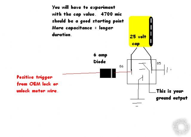
If it's a positive pulse trigger you're using as an input, and you just need a ground output maintained for a short duration after the pulse, you can try this. Just change the values of the resistor and cap to smaller values to get the short 2 sec delay.
If you only need the output as a signal rather and not driving something, you can delete the relay, since the transistor puts the ground out directly.
Can't get much less expensive than that, since the parts should run less than a postage stamp.
Posted By: Kcautosound
Date Posted: October 03, 2009 at 8:33 AM
Thanks for the help guys.
What I'm doing with this is using the door lock motor positive wires to drive relays to produce negative arm and disarm inputs on an alarm. I'm running into some vehicles that they flash too quick of a positive pulse for the alarm to see it. An example problem vehicle I run into is the 2004-08 F150s. The pulse seems to go so fast that it doesn't always allow the relay to fire off a long enough ground out pulse for the alarm to see it, yet if I use a Code Alarm PTM1 pulse timer set to the lowest setting (about 1 1/2 seconds) it works perfect. Just gets expensive when I need two of these timers and they cost me $14.00 each. I use a ton of them. Just trying to maybe create a circuit that I can build and save me some money and time of ordering all these timers in all the time. My distribution can't keep up with my demand for the timers and I've got waiting customers all the time because I'm waiting for the timers to come back in. The PAC TR7 is even more money.
Posted By: i am an idiot
Date Posted: October 03, 2009 at 5:16 PM
Posted By: howie ll
Date Posted: October 03, 2009 at 5:49 PM
Why a 6amp relay? Is it because of the cap?
Posted By: i am an idiot
Date Posted: October 03, 2009 at 6:01 PM
Yes the charging of the cap will take way more than 1 amp of current. A 3 amp diode will probably be OK, he may have to use 10,000 mic worth of capacitor. With that much capacitance, a 3 amp diode will probably hold up, but you know I would rather over engineer it than fix it later.
Posted By: dualsport
Date Posted: October 03, 2009 at 7:52 PM
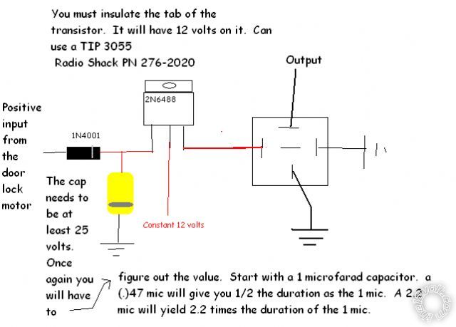
The pulse may be too short to charge up the large capacitance needed to hold the relay energized- it really needs a transistor as the relay driver, especially if there's any limitations on the drive signal current. It'll appear as a near short on the signal at the time of the pulse.
Posted By: i am an idiot
Date Posted: October 03, 2009 at 8:14 PM
He is using the positive voltage from the door lock solenoid. I would probably suggest the wrong transistor for the circuit, so how about a diagram?
Posted By: i am an idiot
Date Posted: October 03, 2009 at 9:00 PM
Posted By: dualsport
Date Posted: October 03, 2009 at 10:40 PM
i am an idiot wrote:
He is using the positive voltage from the door lock solenoid.
Ah, missed that part. Then current's not a problem, it should be plenty.
Posted By: Kcautosound
Date Posted: October 05, 2009 at 3:00 PM
i am an idiot wrote:
Thanks. I will grab some parts, build it and test it.
Posted By: Kcautosound
Date Posted: October 05, 2009 at 5:44 PM
Seems to work fine. I can pretty much do a quick tap to positive with the input wire and it shows a true ground output that my alarm is seeing. When before I was using just a standard relay to flip the positive into a negative output the relay would not produce a strong enough or long enough ground output to be seen by the alarm. With the 2.2 microfarad it still seems quick so I'll try maybe use a larger microfarad capacitor and it should do the trick. I'm thinking the 4.6 mf one I almost grabbed will do just right.
I gutted some old alarm brains that I had for the on-board micro relays. They work great. My plan is to build a small circuit board with two of these circuits (lock & unlock) on it that will fit in the small 2x4 project boxes. I found the same micro PCB relays online for about $0.98 each. Less if I buy more. If I buy a 20 quantity of everything I need I can get the price down to about $8.00 each or less! Quite a bit cheaper than using two $14 to $20 pulse timers. Plus it takes less room than zip-tying the two pulse timers together.
Posted By: Kcautosound
Date Posted: October 06, 2009 at 12:43 PM
OK. I wired it up and tried it with my alarm on the test bench. What I find is that if I simply tap or pulse the input in the circuit it is not enough to produce the signal that I need, however if I hold the input to ground for about a second it will work. The relay clicks but doesn't produce the output that I need.
I put my negative side of my volt meter on the ground out from the relay and connected my positive to obviously the 12 volt positive. I find that if I do a quick tap of 12 volts to the input I will only receive a flash of 8 or so volts on my meter. Yet if I hold it for a second it will give me the full 12 volts showing me I'm getting a full ground out from the relay. I've tried this with a 1, 2.2 and a 4.7 mf capacitor.
I think the problem might be in the bulk of the relay. Anyone know where to find say a lighter weight relay as in lower amperage relay? Maybe I'll try some of the ones that come in the door lock relay packs and see what I get out of them.
Posted By: dualsport
Date Posted: October 06, 2009 at 9:49 PM
There's a certain charge time requirement for the capacitor, so a flick of the wire won't be enough to bring up the voltage with the larger capacitor values. You can't go too small with the cap however, because the transistor you're using needs a small amount of current to operate. If you want to try using a MOSFET, the input impedance is much higher, so only a very small cap is needed, and you can latch it for as long as you need by simply grazing the connection. The MOSFETs work on voltage rather than current, so you can switch those things just by touching it with your finger. However, because of that, they're much more sensitive to damage from static , so they'll require more careful handling.
Posted By: Kcautosound
Date Posted: October 07, 2009 at 12:09 AM
dualsport wrote:
The MOSFETs work on voltage rather than current, so you can switch those things just by touching it with your finger. However, because of that, they're much more sensitive to damage from static , so they'll require more careful handling.
So I guess I'll have to watch scooting my sock covered feed across the carpet just before touching them....lol
|