I just read though the entire relay section in the Basics area and I came back with the best comprehension ever from information I've read on the 'net. Excellent tutorial!
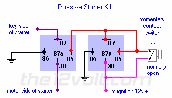
What I would like to see with at least one basic relay circuit using at least 2 relays is a step by step description of the 'logic' behind a relay circuit activation. For example, in the Passive Starter Kll diagram:

When you close the NO momentary switch, 12v 'is available' on pins 85 and 87 of relay #2 and on pin 85 of relay #1. The effect is that 'while the switch is closed', relay #2 is energized, allowing 12v to travel between pins 30 and 87 which in turn 'potentially' energizes relay #1. I say 'potentially' energizes because relay 1 will not pass voltage on the starter wire until you turn the switch on the steering wheel column. Of course, once you turn on this switch, voltage will travel between pins 87 and 30 of relay #1, thus starting the car. None of this would happen though if the entire sequence was not preceeded by closing the momentary NO switch on relay #1.
My question is how does the original 'pulse' from the NO momentary switch on relay #2 maintain relay #1 'potentially' energized after you remove your finger from the switch? Is it that once the starter switch is thrown, relay #1 stays energized regardless of the level of the input on its pin #85? Please explain this because once I understand, I will be able to decipher the more complicated circuits. Thanks!
BTW, has anyone ever seen 'visual' demos of relays in action like in FLASH? I've always been able to completely understand how things work after seeing them function visually.
Left relay is at rest. 30 is connected to 87A. Right relay has an energized coil. Thus pulling on the lever and connecting terminal 30 to terminal 87 instead of 87A.
Mouse over second picture on the following page.
https://www.bcae1.com/relays.htm
Thanks for replying "I am an idiot" and the link to the website is excellent but if you refer to the twin relay diagram on my first post, can you explain how after I pulse the momentary switch on the second relay, the 1st relay stays energized?
Sorry I completely overlooked your question in your original post.
On the right relay 85 and 87 are connected together. When you press the button, it energizes the relay which connects terminal 30 to terminal 87. Since 87 is connected to 85, when you release the switch, voltage no longer goes through the switch, but there is voltage on 87, which in turn keeps the voltage on 85 keeping the relay energized. This will remain the same until the 12 v Ignition feed is turned off.
If you look at the distribution block and notice the fuse sizes, you would have realized that this is for some pretty low current lines. Amp REMOTE wires and Neon lamps.
If your power wire is 4AWG, and you need to interrupt that, you will need a pac-200.


