trying to wire spst 30/40 5 wire relay
Printed From: the12volt.com
Forum Name: Relays
Forum Discription: Relay Diagrams, SPDT Relays, SPST Relays, DPDT Relays, Latching Relays, etc.
URL: https://www.the12volt.com/installbay/forum_posts.asp?tid=118324
Printed Date: May 14, 2026 at 12:31 PM
Topic: trying to wire spst 30/40 5 wire relay
Posted By: johnrhadfield
Subject: trying to wire spst 30/40 5 wire relay
Date Posted: December 07, 2009 at 8:00 PM
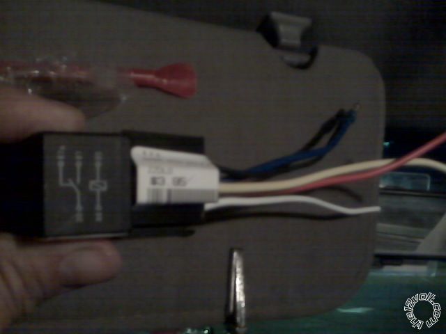 Trying to wire SPST 30/40 5 wire relay to a CEBEK cyclic timer. Onboard the timer is a 5 amp max output relay( I think at least that is what it says on the package). The DC motor I am trying to wire is measured at 7.5 load amps. Thus the reason for trying to wire in the SPST 30/40 relay. Trying to wire SPST 30/40 5 wire relay to a CEBEK cyclic timer. Onboard the timer is a 5 amp max output relay( I think at least that is what it says on the package). The DC motor I am trying to wire is measured at 7.5 load amps. Thus the reason for trying to wire in the SPST 30/40 relay.
So basically I have a 12 volt battery, a simple 7.5 amp DC motor, a 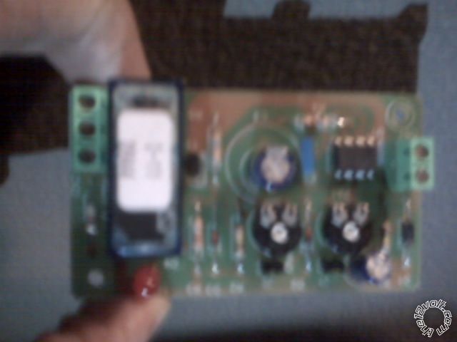 cyclic timer, and a SPST relay. I have no idea what 30 or 86 or 87 or 87a means or how the 5 wires from the relay are wired to the cyclic timer the battery and the motor. I know I need the SPST relay because the motor draws more amps than the timer can handle. cyclic timer, and a SPST relay. I have no idea what 30 or 86 or 87 or 87a means or how the 5 wires from the relay are wired to the cyclic timer the battery and the motor. I know I need the SPST relay because the motor draws more amps than the timer can handle. 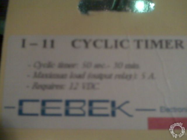
------------- John
Replies:
Posted By: i am an idiot
Date Posted: December 07, 2009 at 8:11 PM
I do not really understand your question, but that happens to me a lot. https://www.the12volt.com/relays/relays.asp Is the link to the relay section on this site. It may show you what you are asking. If not, does the timer put out a ground or a positive voltage? If your camera has a little green flower sybol somewhere on it, select that function and retake the pictures.
Posted By: oldspark
Date Posted: December 07, 2009 at 11:48 PM
The first relay shown is an SPDT (changeover) relay, but it can be used as an SPST by NOT using its "Normally Closed" (relay de-energised) contact #87a. IE - terminal #87 connects to #30 for normal SPST applications.
If the system is 12V (ie, motor, relay, & timer), I assume you merely want to have the timer power/energise the new relay instead of the motor, with the motor driven off the new relay?
The relay is energised with +12V to #86 and gnd to #85 - connect that to timer instead of the motor.
Then connect power through a fuse to #30 & from #87 to motor power (with the motor grounded etc)
As I'mA said above - the relay section has ample info about relay wiring etc.
Posted By: hotwaterwizard
Date Posted: December 09, 2009 at 1:25 AM
I get it 1-11 cyclick timer cebek https://www.mcmelectronics.com/content/ProductData/Spec%20Sheets/28-4741.pdf 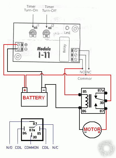
------------- John DeRosa (Hotwaterwizard)
Stockton California
When in doubt, try it out !
Posted By: oldspark
Date Posted: December 09, 2009 at 7:19 AM
Yep - HW-Wizard - you got it!
Thanks for supplying the data. (Man, I still love this site!)
In this case I see no complications (except maybe false triggering as discussed below):
(1) The Cebek timer handles 5A so a mere relay is pittance.
[Even a "huge" 12 Ohm solenoid is only 1A, and the relay pictured (top, above) is probably 60 Ohms or more - ie, ABOVE 12 Ohms is LESS than 1A from V=IR => I=V/R = 12/R (Amps).]
(2) The Cebek timer has a relay output, so no "spike quenching" diode across the added relay's #85 & #86 is required (unless as below..).
(3) Because the added relay (as pictured top, above) has no internal quenching diode, it is not polarity sensitive.
PEDANTIC and at time important - normal convention is that #86 is the +ve and #85 the -ve solenoid connections. This is not important for non-quenched relays or resistive quenched relays, but it is important for diode-quenched relays.
But if you are like me, you will avoid "special" quenched relays and provide your own as part of the socket or wiring.
This can be done after the internal diode has stopped its smoking and has blown open (as a result of reverse-polarity connection of #85 to +V and #86 to -ve aka GND or 0V).
False Triggering...
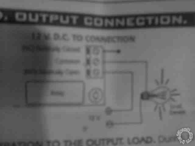
The description in the pdf is a bit vague (page 2, middle):
"you can happen the fluctuation or incorrect output functionment" &
"... you have install the anti-spark...."
.... may be suggesting that an external spike - generated from a 12V bulb and hence moreso from a 12V relay - might cause false-triggering of the Cebek timer module.
If so, transient quenching of the relay solenoid is needed. I recommend a diode.
This is explained somewhere in the relay section on this site, but it merely means a reverse-biased diode across solenoid terminals #85 & #86, where reverse biases means the diode's "-" or line end towards +ve, and the other (Anode) end towards 0V (aka ground or -ve).
If buying diodes, I suggest buy at least 2 diodes - they are usually only about 10c to 30c each.
That way, if the first diode blows because it was wired back to front (and the fuse didn't blow instead), you can wire its replacement correctly. (I call that the "suck & see" approach. Others call it a mistake.)
And most "power" diodes should suffice - eg at least 200V preferably 400V (PIV = Peak Inverse Voltage) with at least 1A (If - forward current) - eg, common IN4004 (1A/400V), IN4007 (1A 1000V), IN5404 (3A, 400V) etc.
Hence the diode can withstand f.ex a 400V transient up to 1A (etc) generated by the relay's inductive solenoid.
I hope I have imparted some knowledge to those as yet still sane.
And again, I thank the HotWaterWizard for doing the hard work!
Posted By: johnrhadfield
Date Posted: December 16, 2009 at 9:24 AM
Wow thanks!
-------------
John
Posted By: johnrhadfield
Date Posted: December 16, 2009 at 8:13 PM
I have just 1 more minor issue with this. The color code of the relay is (from the diagrahm face) : red wire is in the center, yellow wire is foremost(upfront), black wire is to the right, white wire is to the left, and blue wire is in the back. The numbers on the face of the diagrahm(if the picture is too blurry)is: left side top to bottom: 30 top then 86 bottom. right side top to bottom is: 87a top then 87 then 85 bottom 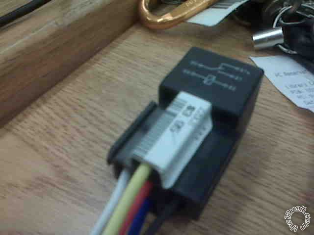
------------- John
Posted By: i am an idiot
Date Posted: December 16, 2009 at 8:24 PM
Unplug the relay there should be numbers next to the terminals. If not, Yellow is on 85, Looks like blue, the bottom wire is 86 White or wire to the left is connected to 87, Red is to 87A, The rightmost wire is to terminal 30
Posted By: tommy...
Date Posted: December 16, 2009 at 8:29 PM
Hey...Whats above the relay in the visor picture...?(off-topic...sorry)
-------------
M.E.C.P & First-Class
Go slow and drink lots of water...Procrastinators' Unite...Tomorrow!
Posted By: johnrhadfield
Date Posted: December 16, 2009 at 8:59 PM
You were right thanks! The numbers were stamped accordingly, on the bottom.
-------------
John
Posted By: howie ll
Date Posted: December 17, 2009 at 2:45 AM
That's the same as the Veleman 111 kit. Used to remove the second pot to emulate a 508d I'm sure I'm, missing something here but it has a built in relay.
Posted By: johnrhadfield
Date Posted: December 19, 2009 at 3:30 PM
Before I connect this, can someone tell me where I should put fuses? I was told by someone not on this forum, that I should put a 7.5 amp fuse on the positive lead of the dc motor(again dcmotor measured has 7.5 working amps). ------------- John
Posted By: johnrhadfield
Date Posted: December 19, 2009 at 3:44 PM
Also, in the above diagrahm the NC does not appear to be connected to a wire. Does that mean that it is to be left alone? John ------------- John
Posted By: oldspark
Date Posted: December 19, 2009 at 6:00 PM
NC is left alone. (Unless you want something connected when the relay is off.)
A fuse should be placed at the start of the wiring to protect it - ie, at the battery. That might be a 10A fuse - ie, to handle 7.5 working Amps plus the draw of the timer & relay +ie, 80ma + 250mA = 330mA ~8A.
The motor might have an inrush current current that may exceed 8A or 10A. That may require a slow-blow fuse. Try it and see.
You might decide to run 3 fuses - eh, a plenty-big 20A at the battery (to match or protect its wire), a 100-250mA for the timer, and whatever for the motor.
If the motor uses 7.5A, you would NOT use a 7.5A fuse. Normally fuses would be sized to run at ~70% capacity, hence you'd probably want a 10A fuse.
The question is, what size fuse is needed to protect the motor - ie, what value of over-current will fry it? (But that is probably something that required a boosted voltage.....)
Posted By: howie ll
Date Posted: December 19, 2009 at 6:12 PM
Exactly word for word what I would have said Peter except this has gone on too long it's only a bloody relay. P.S. My rules state fuse to be securely mounted no more than 10cm (4") from power source e.g. battery.
|