diagram, making my own remote start
Printed From: the12volt.com
Forum Name: Relays
Forum Discription: Relay Diagrams, SPDT Relays, SPST Relays, DPDT Relays, Latching Relays, etc.
URL: https://www.the12volt.com/installbay/forum_posts.asp?tid=119045
Printed Date: May 13, 2026 at 11:09 PM
Topic: diagram, making my own remote start
Posted By: stup
Subject: diagram, making my own remote start
Date Posted: January 02, 2010 at 9:27 PM
I am looking for a little advice to see if what I've got so far will work.
A Little background on the project: I am trying to build my own remote start system using the factory key fobs. This is in a 1998 Ford Explorer. When you press the lock button on the fob once, it locks the doors, press it a second time within 5 seconds and it honks once, press it again within 5 seconds and it honks a second time. What I am trying to accomplish is using 2 honk pulses to start the remote start circuit. Now it is possible that I am going at this the wrong way, but this is what I have come up with to handle the 2 honk pulses:
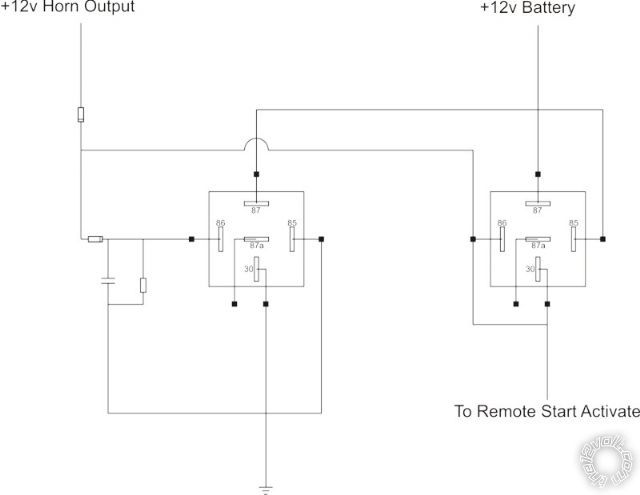
In theory, the first horn honk should turn on the first relay, and the capacitor should hold it open for a set amount of time (to be determined later). If the horn is honked again in that time, the second relay should latch closed because it now has ground from the first relay. So, will this work?
Note: I know I need to add a diode to the second relay between pin 30 and pin 86 to prevent remote start from activating off of the first horn press. I also know I should put diodes across the relay coils. I am just trying to see if this circuit should work before I put in some time and money prototyping it.
Replies:
Posted By: howie ll
Date Posted: January 03, 2010 at 2:37 AM
Yes but "bench test" it first. Incidentally, some DEI add on product rely on a double signal to start and stop as their default but you can change this so you only need 1 relay or a polarity flip transistor/resistor/diode arrangement to send this signal to the unit! Also if the horn push feeds a neg anywhere, no relay, just a 1amp diode for safety sake.
Posted By: stup
Date Posted: January 03, 2010 at 8:25 PM
I did a test run and when I trigger the first, the second triggers at the same time. I think the relay is too fast and is providing the ground before the trigger goes away. Is there any way around this?
Posted By: el ranchero
Date Posted: January 03, 2010 at 8:39 PM
wow, cool, but how are this two relays going to operate the ign, you need a timer to hold the relay u are using to keep the ign on, i guess the second relay is used to crank the starter, if u are doing this to experiment good, but i wouldnt advice on using it in a permanet installation. but hey good luck, i remember when i tried to do the same thing and i also tried to do auto matic window rollups by putting microswitches at the ends of the window, didnt work but its always good to experiment , and always use fuses. ------------- rocker
Posted By: el ranchero
Date Posted: January 03, 2010 at 8:41 PM
never mind i totally misundertood the diagram u posted,  ------------- rocker
Posted By: dualsport
Date Posted: January 03, 2010 at 9:54 PM
It'd be easy with solid state circuitry; trying to do it with just relays and passive components is going to be tough. I'm pretty sure it was covered in a previous post, if you're willing to get into that kind of thing.
Posted By: stup
Date Posted: January 03, 2010 at 10:13 PM
well, i have diodes, relays, resistors, capacitors and transistors already. i was hoping to build the circuit without buying anything new.
Posted By: dualsport
Date Posted: January 03, 2010 at 10:43 PM
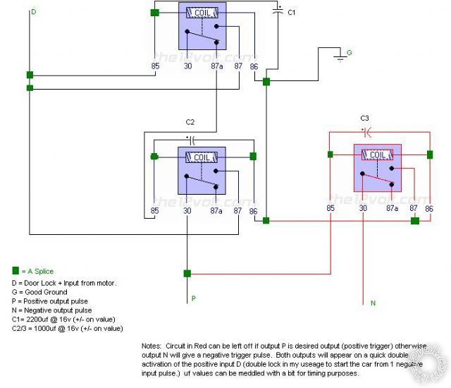
Read through this prior post and you should be able to work it out similarly-
Posted By: stup
Date Posted: January 03, 2010 at 11:26 PM
dualsport wrote:
Read through this prior post and you should be able to work it out similarly-
well, with a little modification to the design, i think it will work for what i need, thanks for that
Posted By: festeraddams
Date Posted: January 16, 2010 at 10:59 PM
 ------------- The light bulbs not burned out, it is just full of dark!
Posted By: festeraddams
Date Posted: January 16, 2010 at 11:04 PM
Both of your relays are triggered off the horn output, this was a circuit I used just last week to trigger a DEI single pulse input R/S (Valet) system for a 2000 Town and Country, I used the door lock motor + pulse to activate the circuit. You had to lock the doors quickly 2 times to activate the output for a bit. Good luck.
-------------
The light bulbs not burned out, it is just full of dark!
|