intercom wiring
Printed From: the12volt.com
Forum Name: Relays
Forum Discription: Relay Diagrams, SPDT Relays, SPST Relays, DPDT Relays, Latching Relays, etc.
URL: https://www.the12volt.com/installbay/forum_posts.asp?tid=119206
Printed Date: May 13, 2026 at 9:03 PM
Topic: intercom wiring
Posted By: sumnerhousesf
Subject: intercom wiring
Date Posted: January 09, 2010 at 6:10 PM
I am trying to wire an intercom and a keypad to work together on the same electric lock for an entry gate. I have tried the configuration below in Diagram A:

Both the Keypad and the doorfone work off of a 12v DC transformer. In the above diagram A only the keypad will unlock the lock. When I try to unlock with the Doorfone, you can hear it click and working, but nothing happens. For the Doorfone, power is being run to the negative(-) end of the doorstrike contact. The doorfone works when i connect it directly to the lock without the keypad. I assume the doorfone has an open collector transistor to short the - side to the negative supply of the keylock when connected directly. The doorfone only seems to work if both the + and - door strike contacts are connected to the lock.
My question is can I make both doorfone and keypad work with this configuration? Do I need to add a separate DPDT relay? If so, what would the wiring look like. Thanks for any help on this!
Replies:
Posted By: i am an idiot
Date Posted: January 09, 2010 at 8:12 PM
What is the maximum current output capability of the door phone? What are the current requirements of the 16volt lock? Are you sure the door phone module puts out 12 volts? Or is it maybe a 5volt output?
Posted By: sumnerhousesf
Date Posted: January 09, 2010 at 9:23 PM
The door stike uses 8-16VAC or 3-6VDC.
When wired individually, the doorfone will open the lock fine. My problem is getting both units to work on the same lock.
Posted By: i am an idiot
Date Posted: January 09, 2010 at 9:36 PM
It has to be a bad relay or bad connection on the keypad. Can you check continuity between the output of the door phone to the electric lock. If it does not show a good connection, check the solder joints and traces on the back of the board of the Keypad.
Posted By: KPierson
Date Posted: January 09, 2010 at 11:23 PM
The "not used" contact on the dry relay contact should be connected to 12vdc
-------------
Kevin Pierson
Posted By: dualsport
Date Posted: January 10, 2010 at 6:19 AM
yep, the dry contacts designation on the doorfone means there's no connection from them to power or ground, so you have to supply it externally through that contact you left open.
How it came about that they're called "dry" is a mystery. And if they're not "dry" then what are they? 
Posted By: sumnerhousesf
Date Posted: January 10, 2010 at 1:46 PM
Thanks so much for the responses. Here is something else confusing for me. On the doorfone, the - dry contact has power running to it all the time. When I connect the - dry contact to the keypad at the NC output, it activates the lock and keeps the lock open. This leads me to believe that the + and - dry contacts work together to short the connection and open the lock.
In the above diagram if I connect the - dry contact to the 12VDC wont that create a short since there is current running through the - contact? How should I properly wire this? just a bit confused here.
Posted By: KPierson
Date Posted: January 10, 2010 at 1:55 PM
If it truely has a "dry contact" then there should be no voltage on either contact unless you put it there (hence the name "dry"). The dry contact should be a C and a NO (or NC depending on the hardware). In a dry contact you don't have a (-) and a (+) as it is simply a switch so whatever you put in you'll get out. ------------- Kevin Pierson
Posted By: dualsport
Date Posted: January 10, 2010 at 3:56 PM
Like Kevin said, the dry contacts shouldn't show anything on them if left unconnected. We were assuming the description was accurate, but after poking around a bit, it appears you're missing the door strike controller as shown in this diagram that I found - (your other thread on gardenweb also came up- 
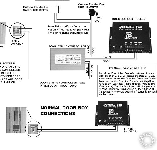
The extra door strike controller shown is probably a relay, so your Door Fone output (which is NOT a dry contact but a low output control for a relay) is not able to drive the door solenoid directly.
If you check that the red output from the door fone is 12V, you can simply add a relay and the COM and NO terminals (30 and 87) will provide the "dry" contacts you need for your connection.
Posted By: i am an idiot
Date Posted: January 10, 2010 at 4:12 PM
sumnerhousesf wrote:
When wired individually, the doorfone will open the lock fine. My problem is getting both units to work on the same lock.
Posted By: dualsport
Date Posted: January 10, 2010 at 4:32 PM
Good point- maybe the unit he has isn't as shown in the diagram I found. Either way, it's not as described. Certainly a set of dry contacts can't drive a door strike, so they're definitely not dry contacts.
If they can drive the strike when directly connected, but can't do it with just the red output connected, then it seems the thing to try would be to see what that black output is doing. Possibly just need to connect it to the ground side of the door strike. Then it's the same as a direct connection. If it doesn't work then, there's more going on in there that we'd need to find out about.
Posted By: sumnerhousesf
Date Posted: January 10, 2010 at 4:37 PM
Yes when wired individually both systems work. The diagram you show is for a different model of doorfone. I have a DP28 2 button intercom with a built in door strike controller so I dont need the extra box.
You may have something there though with the extra relay. Would I need a SPDT or DPDT relay for this? thanks a lot
Posted By: i am an idiot
Date Posted: January 10, 2010 at 4:45 PM
If the unit will open the lock when connected without the keypad, the relay should not be neccesary. Hey I have an idea, check for continuity between the common and the normally closed connections of the keypad. You may have a defective relay or an open trace or a bad connection on the back of the circuit board of the keypad.
Posted By: dualsport
Date Posted: January 10, 2010 at 4:47 PM
Can you make a couple measurements with a meter to see if we can see what it's actually putting out?
In your other thread, you indicated if you swap the wire around so that you're running the black wire to the keypad, the door strike is continually energized. This indicates the black output actually has 12V on it continually.
The red wire probably is a shunt to ground when the doorfone is active.
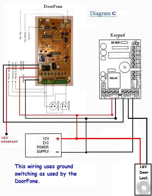
If this is the case, then you'd just need to change it around to use ground switching for your door strike rather than (+) switching.
Posted By: dualsport
Date Posted: January 10, 2010 at 4:48 PM
I assume you know how to reconfigure it for ground switching, but if not, we could draw it up for you-
Posted By: sumnerhousesf
Date Posted: January 10, 2010 at 5:08 PM
Yes the - door contact outputs 12v continually. Sorry I am a novice at this hence so many questions. Can you tell me how to wire it for ground switching with both units connected?
Posted By: dualsport
Date Posted: January 10, 2010 at 5:34 PM
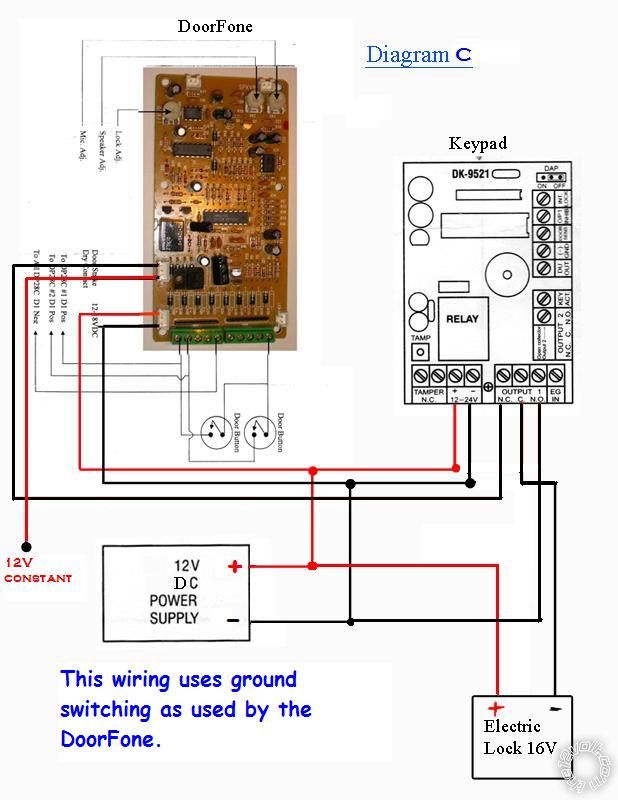
Note I changed the colors of the wires coming out from the door fone, but the terminals should be how you found it originally-
The red wire is now the +12V constant, and the black is the switched ground output-
Posted By: sumnerhousesf
Date Posted: January 10, 2010 at 6:00 PM
OMG! that's genius. Thanks for the wonderful diagram. I will try it and let you know how it goes. I would have never been able to figure it out on my own, but it makes perfect sense. I'm hopeful about this one
Posted By: dualsport
Date Posted: January 10, 2010 at 6:10 PM
And now you have a customized door lock -
Hope it works out!
|