time delay off circuit
Printed From: the12volt.com
Forum Name: Relays
Forum Discription: Relay Diagrams, SPDT Relays, SPST Relays, DPDT Relays, Latching Relays, etc.
URL: https://www.the12volt.com/installbay/forum_posts.asp?tid=119510
Printed Date: March 04, 2026 at 4:23 PM
Topic: time delay off circuit
Posted By: zmedak5
Subject: time delay off circuit
Date Posted: January 21, 2010 at 6:44 AM
Hi guys, i need 12v circuit who will after connecting 12Vpower supply make a 2sec positive output and then off, untill reconnect power supply. Please help, Best regards from Croatia!
Replies:
Posted By: zmedak5
Date Posted: January 21, 2010 at 6:52 AM
i forget output current max 3A.
Posted By: zmedak5
Date Posted: January 21, 2010 at 7:32 AM
And without relay!
sorry to post again...
Posted By: hotwaterwizard
Date Posted: January 22, 2010 at 8:46 AM
 ------------- John DeRosa (Hotwaterwizard)
Stockton California
When in doubt, try it out !
Posted By: zmedak5
Date Posted: January 22, 2010 at 11:29 AM
Thank you friend, bud you don*t understand my problem!
I need circuit who will after connecting 12v on input, produce 1sec positive output.
I need to power BMW e46 projectors.
https://www.wolstentech.com/products/bixenon/bixenon.php
something like that!
Posted By: hotwaterwizard
Date Posted: January 23, 2010 at 6:19 PM
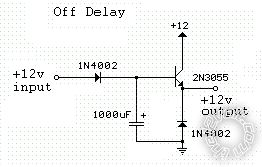
Have you tried this circuit? Delayed off means it turns on with power then after the timing cycle it turns off. ------------- John DeRosa (Hotwaterwizard)
Stockton California
When in doubt, try it out !
Posted By: i am an idiot
Date Posted: January 23, 2010 at 7:53 PM
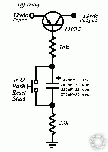
I think his input wire goes hot and remains hot for a while. He needs only a 2 second pulse when his input wire goes positive. From what I am seeing, your device will have output the entire time the input wire is positive, then the cap will keep it on additional time after 12 volts is removed from the input wire. The following picture will do what you need it to do. However it will take a 4700 microfarad capacitor to give you near or just above 2 seconds for your pulse.
| Constant to Momentary Output () |
The capacitor allows the coil of the relay to be energized until the capacitor stores a charge, thus de-energizing the coil. The resistor bleeds off the charge of the capacitor when positive voltage is removed from the other side of the coil. You can increase the output time by simply changing the value of the capacitor. This one will give you about a 1/2 second output.
 |
Posted By: hotwaterwizard
Date Posted: January 24, 2010 at 4:32 AM
You are right. He also wants no relay though. ------------- John DeRosa (Hotwaterwizard)
Stockton California
When in doubt, try it out !
Posted By: hotwaterwizard
Date Posted: January 24, 2010 at 5:14 AM
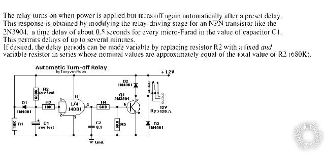
How about this one? https://www.sentex.net/~mec1995/gadgets/relays/relays.html 
------------- John DeRosa (Hotwaterwizard)
Stockton California
When in doubt, try it out !
Posted By: hotwaterwizard
Date Posted: January 24, 2010 at 5:32 AM
 ------------- John DeRosa (Hotwaterwizard)
Stockton California
When in doubt, try it out !
Posted By: i am an idiot
Date Posted: January 24, 2010 at 8:45 AM
Is there any way to use the logic behind the relay diagram I posted to work with a transistor? You would have to use a resistor before the capacitor and the base or gate of a transistor. Having the transistor on only until the cap has charged. I can do it opposite of what it needs to be. It would be off until the cap charged then turn on and remain on. It should be possible.
Posted By: dualsport
Date Posted: January 24, 2010 at 9:18 PM
zmedak5 wrote:
Thank you friend, bud you don*t understand my problem!
I need circuit who will after connecting 12v on input, produce 1sec positive output.
I need to power BMW e46 projectors.
https://www.wolstentech.com/products/bixenon/bixenon.php
something like that!
Something like that, or exactly like that? Are you trying to make the controller circuit described there for driving the high beam solenoid or for something else?
The controller they're offering on that page is not putting out a 12V pulse but a negative one (ground switched), so what you're describing is different.
It'd actually be easy to do, but if that's what you're after, you'd really be hard pressed to do it much cheaper or better than what they're offering for $8. The little circuit board with the connectors looks like a neat and tidy solution for the price.
Posted By: hotwaterwizard
Date Posted: January 25, 2010 at 12:37 AM
 ------------- John DeRosa (Hotwaterwizard)
Stockton California
When in doubt, try it out !
Posted By: zmedak5
Date Posted: January 25, 2010 at 11:16 PM
dualsport wrote:
zmedak5 wrote:
Thank you friend, bud you don*t understand my problem!
I need circuit who will after connecting 12v on input, produce 1sec positive output.
I need to power BMW e46 projectors.
https://www.wolstentech.com/products/bixenon/bixenon.php
something like that!
Something like that, or exactly like that? Are you trying to make the controller circuit described there for driving the high beam solenoid or for something else?
The controller they're offering on that page is not putting out a 12V pulse but a negative one (ground switched), so what you're describing is different.
It'd actually be easy to do, but if that's what you're after, you'd really be hard pressed to do it much cheaper or better than what they're offering for $8. The little circuit board with the connectors looks like a neat and tidy solution for the price.
In that solenoid there are two solenoid, the ground is common and there are two positive, first one for holding (the little one) and the big one for momentary pulling.
That little circuit board is easy to buy for you, not for me, i am for Europe/Croatia and that guy is USA (delivery time 30 days, i need that driver now...)
Posted By: dualsport
Date Posted: January 26, 2010 at 9:59 PM
If you're working with the same solenoid described by that site with the circuit board, the 12V is common, not the ground. If you read the description in the troubleshooting page, he connects the 12V, then connects the black or green wires to actuate the solenoid. It would have to be ground, or otherwise it's not getting any power if it was connecting 12V to the black or green wires.
You may be able to do it the way you want also, as long as the solenoid doesn't care about polarity.
It's easier to switch ground so unless you have a good reason to do otherwise, you should do the same as that circuit board does.
I'd guess there's really only a single solenoid, with the green wire connection running through a resistor in series to limit the current for the hold function. The black goes directly to the solenoid for full power when pulling it in initially. I don't think they'd have a separate solenoid just for that purpose, but if you have one in your hand, you'd be better able to confirm that. Measure the resistance between the green and black wires and see what it shows.
Are you able to get transistors and other parts there to build circuits?
Posted By: oldspark
Date Posted: January 27, 2010 at 12:51 AM
I would have thought a circuit similar to the complexity of our excited hydronium oxide wizard (hotwaterwizard Esq.) would suffice....
IE - through a capacitor and resistor to a FET with a shunt/discharge resistor & reverse-biased diode to ground (after the cap - for RC-decay, and -ve pulse quenching).
If true on-off is needed (rather than a possible slow off), then more is needed - but a 20A-60A FET is only a few dollars.
Not that I understand its application. At first I thought is was to momentarily turn on HIDs (bad!), but I presume it's for the solenoid in that gay or bixenon link?
But in that case, why not modify Wolsten's circuit which seems to utilise a FET for such switching?
Posted By: dualsport
Date Posted: January 27, 2010 at 2:49 AM
That should exactly be all that's needed, FET, cap, resistor, and diode. The FET would be driven through a series connected cap to turn on upon initial application of power, then drain down to ground through the resistor, which turns it off again. The diode would shunt any turn off transient produced by the solenoid (though it should be reduced due to the hold current.
The HID assembly has a solenoid that moves a shutter to set its position to either shield the arc for the low beam setting or expose it for high beam.
As with a relay, the pull in current is higher than the hold current, so the purpose of this exercise is to switch the high current in momentarily until the solenoid engages, and then release it to the low current line to hold the position. The problem with applying full power all the time is that it could overheat the solenoid; possibly it's not rated for continuous duty at full power.
This really could be done even with just a cap and resistor wired in parallel, and wiring them in series with the power input. The cap would deliver the surge of current needed to pull in the solenoid or relay, and then the resistor would provide the hold current after the cap discharges. It'd just need a larger cap due to the direct coil drive without solid state drive. But simple- just select a cap large enough to energize it, and select the resistor as required to maintain the hold current.
This could be used to lower the current draw of standard relays as well, to save power. It would be useful for applications where the relay is on continuously for long periods, and you want to save some battery power.
Posted By: zmedak5
Date Posted: February 08, 2010 at 4:37 AM
You were wright! i need negative output for these solenoids...
Posted By: dualsport
Date Posted: February 16, 2010 at 9:12 PM
zmedak5 wrote:
i need negative output for these solenoids...
Here's more details on it-
The direct input to the solenoid draws about 2.5A, and the hold current going to the second input is about 300mA. There are separate taps on the solenoid coil, so it can use either the hefty 2.5A current to pull it in initially, or the low powered input to maintain and hold the shutter in the open position. About 30W vs. 3.5W, which is why you don't want to use full power continuously, since it'd draw nearly as much power as the HID lamp itself.
The circuit would just need two inputs, the switched 12V from the high beam control, and a ground.
There will be three outputs, with the 12V switched passing directly to the +12V terminal of the projector solenoid circuit (the middle of the 3 pin connector), and the ground passing directly to the hold terminal of the projector solenoid circuit (the terminal pin closest to the solenoid.)
The switched output to actuate the solenoid initially will be the drain output of the FET. (FET has 3 pins, Gate, Source, and Drain)
Connect it to the remaining pin of the projector solenoid circuit board.
Ground the Source terminal of the FET.
For the gate of the FET, you'd have a series connected capacitor connected between it and the switched high beam input. Add a resistor between the Gate and ground to allow the cap to charge up when the high beam is turned on, resulting in the FET being turned off.
Add a suppression diode across the FET source and drain pins, and you should have it.
Select a power MOSFET that'll handle the 2.5A, and pick the cap/resistor combination to give you a long enough output pulse to engage the solenoid; not really too critical. Anything above 100ms probably would do it, you could go with 1/4 second and it'd be fine.
Any pulse longer than that is just wasted, since the solenoid closes in a split second, and only the 300mA hold current is needed beyond that. I'd try 1uF and 100k as a start. If you use a polarized cap, positive goes towards the switched 12V highbeam input. Just increase the size of the cap if you want a longer pulse time.
Posted By: zmedak5
Date Posted: February 22, 2010 at 1:07 AM
Please draw.
Posted By: dualsport
Date Posted: February 23, 2010 at 9:18 AM

Added D2 to protect the MOSFET when the solenoid turns off, although it probably isn't needed since the driver doesn't turn off quickly. For another couple of pennies you may as well add it in.
I don't know what kind of parts you have at your disposal, so select a MOSFET to handle the 2.5A current, you can search for one on mouser.com or digikey.com if you're able to buy parts that way, or find one from whatever sources you have available over there. The 2.5A is just a momentary peak current, so you could get away with a smaller rating since it's not on very long, and it won't heat up much from it.
This provides a momentary (-) pulse to the strong pull in coil and then shuts it back off, leaving the hold coil to keep the shutter open until you turn off the high beam switch again.
Posted By: zmedak5
Date Posted: March 28, 2010 at 11:40 PM
Friend,
i build the circuit bud not work...
I use Mosfet IRFZ44, changing values of the capacitor and resistor, but not work. No momentary output!
Posted By: dualsport
Date Posted: March 29, 2010 at 12:10 AM
The momentary output is a ground connection- how are you trying to test it? If you put a test load like a lamp across the "High Beam Solenoid" and the "Momentary" outputs, then connect 12V to between the "High Beam Sw Control" and "Ground", you should see it light up briefly and then go out.
What did you change the values to?
You can test if you have your transistor and circuit connected correctly if you jumper across the cap (shorting it out) and apply your voltage input, your test light should light up for as long as you keep it applied. If it doesn't, you may have something hooked up wrong or a bad component.
Posted By: zmedak5
Date Posted: March 31, 2010 at 1:55 AM
not working...
Posted By: dualsport
Date Posted: March 31, 2010 at 2:20 AM
zmedak5 wrote:
That little circuit board is easy to buy for you, not for me, i am for Europe/Croatia and that guy is USA (delivery time 30 days, i need that driver now...)
Even through you needed it in January, if you order it today it'd might be fastest way for you to get it done. Or maybe you can find someone over there that could wire it up for you-
Posted By: zmedak5
Date Posted: April 01, 2010 at 12:45 AM
Friend you were wright. I bought set of MOSFETs with fabric mistake.
I use another one and everything works fine.
  
Thanks
Posted By: dualsport
Date Posted: April 01, 2010 at 8:31 AM
Good to hear- nice job fitting it right onto the board. The MOSFET is a bit bigger than you need for this, but it's fine.
|