dei528t relay w/ hid kit
Printed From: the12volt.com
Forum Name: Relays
Forum Discription: Relay Diagrams, SPDT Relays, SPST Relays, DPDT Relays, Latching Relays, etc.
URL: https://www.the12volt.com/installbay/forum_posts.asp?tid=119723
Printed Date: May 13, 2026 at 2:55 AM
Topic: dei528t relay w/ hid kit
Posted By: viperspike
Subject: dei528t relay w/ hid kit
Date Posted: January 28, 2010 at 11:07 PM
I am installing an HID kit on a 06 GSXR 1000 Motorcycle, and am trying to install a delay from initial power on, to firing of the HID.
I have hard wired the positive wire from the batt to the HID ballast, and am using the existing +12v headlight power wire to signal a relay which provides a ground signal for the HID ballast
I ordered a DEI528 relay to achieve a delayed signal to the grounding relay. However it seems that I will have to use the normally closed wires on the 528T to keep the ground relay actuated once the delay has passed.
Question #1 will power make it through the normally closed contacts and actuate the grounding relay before the 528T can actuate open (delay mode)?
Question #2-if power will make it past the 528T and actuate the ground relay before it can open, how do I delay the grounding relay actuation (if possible)
Thanks in advance for your help with this :) - Shawn
(sorry for the bad diagram) 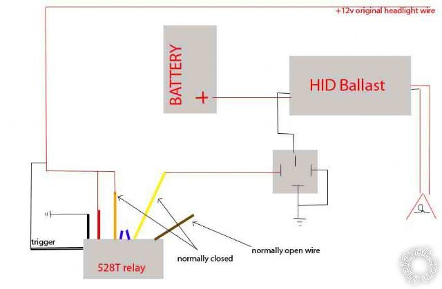
Replies:
Posted By: dualsport
Date Posted: January 29, 2010 at 7:08 PM
I wired up a relay circuit with my HID lights so that the lights remain off until after I crank the bike and start it up, so I don't need a fixed delay. It uses the starter motor as the control trigger input. You might consider that option if you don't have to do it with the timer.
Posted By: viperspike
Date Posted: January 29, 2010 at 10:52 PM
I already have the one grounding relay installed, and recently purchased the 528t Relay, so if I can use the 528T in series I would like to.
What wire did you find that is +12v only after engine start? Thanks, Shawn
Posted By: dualsport
Date Posted: January 29, 2010 at 11:57 PM
It's not a wire on the bike that is 12V after start, instead it's a relay circuit that uses the starter motor input to provide power to the HIDs only after the starter is cranked and released. If the ignition is switched on, the lights stay off until after you crank the bike and release the starter button. The lights stay off while cranking to maximize power for the starter.
It uses two relays, and the starter motor is used as a virtual ground for the relay when the starter button is released.
I'll see if I can dig up the diagram if you're interested- -
Posted By: viperspike
Date Posted: January 30, 2010 at 12:23 AM
yes please :)
Thanks, Shawn
Posted By: dualsport
Date Posted: January 30, 2010 at 12:35 AM

You just need four connections with this circuit, you'll use it to interrupt the power to the HID lights shown at the green and orange markers, and connect to your starter motor at the pink marker, and ground at the black marker.
The starter motor pulse when you push the start button energizes the upper relay in latching configuration (this can be just a small relay).
When you release the starter, the pink marker immediately becomes a ground, and provides the 12V differential across the coil on the bottom relay to switch it on.
Note it's the bottom relay that needs to be large enough to handle whatever you're switching. I have it controlling all the lighting on the bike, along with the HID headlights.
When you switch off the bike, the power is cut off from the green marker, and the relays open up, and you're back where you started.
I have another modification to it that adds an extra delay after the starter button is released before switching on the headlights, in the event your bike isn't running well enough to start on the first crank. Mine starts on the first crank cycle so I haven't bothered changing it yet.
Posted By: oldspark
Date Posted: January 30, 2010 at 1:28 AM
The other way is charge sensing and that is easy if the system has a charge light.
And the circuit above is so close to a single-relay latching circuit (where a standard SPST relay keeps itself energised) except that the relay energises AFTER cranking - and that needs an extra relay.
(IE - if charge activated, it is only one relay. For loads to remain on after stalling - like PCs etc - latching is easy to add.)
Posted By: viperspike
Date Posted: January 30, 2010 at 11:53 AM
does anyone know if my original diagram will work correctly, or should I go in the direction suggested? - Thanks, Shawn
Posted By: viperspike
Date Posted: February 04, 2010 at 3:47 PM
What if I put a 470uf cap in parallel across the coil of the relay connected to the HID ballast? would that create a short delay in it's turn on, or do I need a capacitor and resistor? - Thanks - Shawn
Posted By: oldspark
Date Posted: February 04, 2010 at 4:43 PM
Only after a resistor - see the delay examples under relays. (That's for plan relays...)
Posted By: viperspike
Date Posted: February 04, 2010 at 11:05 PM
OK! I figured it out, finally! I'll post my diagram and hopefully help others from days of frustration. - Shawn
Posted By: dualsport
Date Posted: February 06, 2010 at 3:12 PM
You might want to check the voltage on the relay after it turns on.
Depending on the relay you're using, it's going to drop across your resistor. Not having full drive voltage on the relay reduces the force on the relay contacts, which may cause problems if you're pulling a lot of current through them.
Posted By: viperspike
Date Posted: February 09, 2010 at 4:26 AM
I was using 2 9V batteries in series to test my circut off the bike, however upon using 12V it did not work properly. First, I believe that the capacitor has to charge to about 7 volts **before the timer (MK111) will start the delay cycle. I am now using a 450Pf capacitor with a 10ohm resistor. This configuration will allow me to turn the key on, but requires an extremely long time to charge the capacitor (ensuring the headlight does not come on before engine start). However after engine start, the capacitor charges in a few seconds, delay engages, and everything works normal after delay using 50V 470Pf capacitor with 10ohm resistor. - Shawn
Posted By: dualsport
Date Posted: February 09, 2010 at 6:38 AM
viperspike wrote:
I was using 2 9V batteries in series to test my circut off the bike, however upon using 12V it did not work properly. First, I believe that the capacitor has to charge to about 7 volts **before the timer (MK111) will start the delay cycle. I am now using a 450Pf capacitor with a 10ohm resistor.
Is that pF as in pico Farad? That's a very small value that would have almost no effect here. But if it's a PF as in peta Farad, that's immense- Is that what's marked on it?
Anyway, it's the resistor that determines the amount of current that the relay gets, so that's why you found that you had to drop the value down from 150 to 10. That should allow enough voltage to power the relay, with the size of the cap affecting the delay.
Posted By: viperspike
Date Posted: February 10, 2010 at 12:03 AM
upon testing the original 150ohm/4700pF cap the MK111 led would stay on forever and never close the circuit. (stayed in the delay position)
I then added another 150ohm resistor in parallel dropping the resistance to ~70 and the MK111 still would not close.
So I added a third resistor dropping to ~30ohms = same result
Tried a 2200pf Capacitor w 30ohms = same result (stuck in open position forever)
Tried a 470pf capacitor with 10ohm and found it stayed open forever with the bike off, but with engine running the alternator charges the system to ~14 or so the MK111 delays for about 30sec (its slightly adjustable, not like without the cap/resistor combo) and upon closing, the ground relay is delayed ~1/2 second.
!! the 470pf cap I used is a 50V capacitor, that could be my problem, but it seems to work okay - Shawn
Posted By: viperspike
Date Posted: February 19, 2010 at 7:46 AM
Instead of a capacitor and resistor would a 5.1V zener diode to prevent unwanted momentary actuation of the second (grounding) relay? Any thoughts? - Thanks - Shawn
Posted By: dualsport
Date Posted: February 19, 2010 at 8:11 AM
Not sure what you'd do with a zener. How are you planning to use one here?
If you really want to do a fixed time delay you should use transistor drivers with resistor/cap to set the timing. Problem you'd have with the setup you're using is the reduced relay coil drive voltage. If it's too low, it reduces the contact force on the relay, and increases resistance. Get to a certain point, and the contact will heat up and eventually fail because it'll degrade and pull more current because of the lower voltage. HID ballasts are a constant power device, so if you feed it lower voltage, it'll start drawing more and more current to compensate. If your relay contact starts down the slope, it'll get worse and worse as it's called on to pass more current even as it's less able to do so.
I suspect your circuit isn't actually using the capacitor at all, but just the reduced voltage causing the weak relay pull in. When you start the bike, the vibrations may be shaking the relay and allowing it to close the contacts.
My recommendation would be just to simply install a switch to control it manually or use the relay circuit posted earlier to use the starting of the bike to switch in the HID power.
Posted By: oldspark
Date Posted: February 19, 2010 at 8:21 AM
Thanks Dual - you saved me saying it.
Not that I ever like time delays involving the relay coil (it should be buffered via a transistor or FET, from an RC or timer circuit), but a resistor in series with a relay (coil) is also trouble - unless you have a BIG cap (usually electrolytic which is expensive, and has limited life).
Posted By: dualsport
Date Posted: February 19, 2010 at 10:52 AM
oldspark wrote:
BIG cap
Yeah, I know it's popular to use the BIG cap here for delays mainly because it seems simpler and more intuitive, but it's probably just because MOSFETs are not that familiar a device to some. Plus it's in the list of suggested relay configurations here, so it's sorta got the seal of approval. Using a 20 cent transistor along with some penny parts for the relay driver in those applications is so much better than a big moosey cap it just seems odd why it's not SOP.
Posted By: oldspark
Date Posted: February 19, 2010 at 5:50 PM
Thanks again Dual.
Not that I mention MOSFETs for simple RC delays - I'm not that good on circuitry either, and FETs are hi-impedance voltage switched devices (unlike lower current-switched transistors) - but they seem excellent for hi-current on-off applications.
IE - I often see 60A devices for a few dollars (AUD$2). And being hi-impedance inputs, current-drive is not a problem. (That should make it simpler for RC control as the FET itself is usually insignificant as an RC drain.)
Alas it's one of those "break even" decisions....
When is a timing buffer and its complication (transistor(s) etc, else a 555 or other circuits) better than relay chirp and unreliability, big caps & cost, difficult adjustment, etc?
Posted By: viperspike
Date Posted: February 19, 2010 at 11:46 PM
Here is my original problem. Relay #1 is a velleman MK-111, relay #2 is a radioshack 30amp 12v relay.
upon getting +12v from the headlight will relay #1 open in time to prevent momentary closure of relay #2? 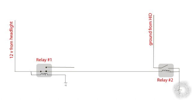
Posted By: dualsport
Date Posted: February 20, 2010 at 7:33 AM
That Velleman MK-111 kit is going to continually turn your headlight on and off since it isn't a one shot circuit.
It wouldn't work as is because your headlight would be on all the time if you use the NC-COM contacts and you'd only get a short pulse if you used the NO-COM contacts.
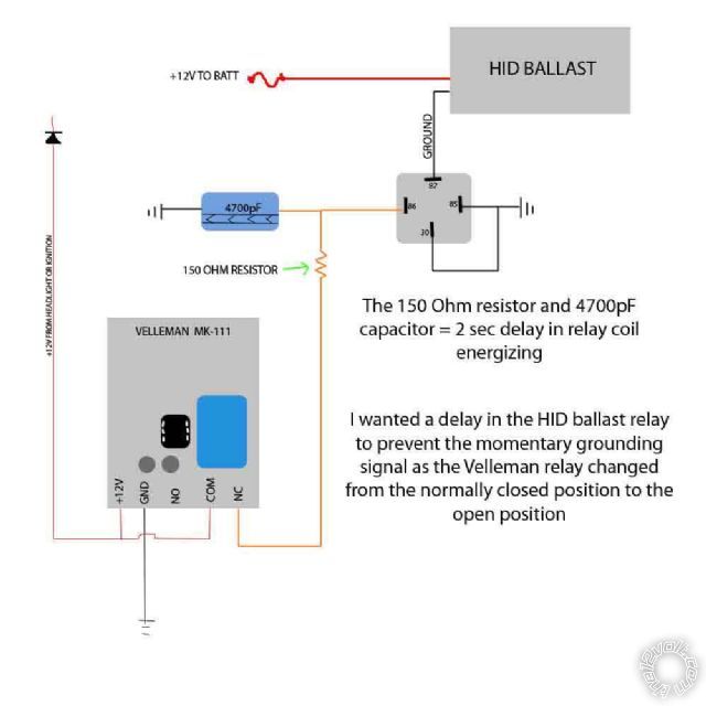
This is all that's needed to insert a delay in the switched output.

Just change the values of the cap and resistor for whatever delay time you want. Larger cap and resistor values increase the delay time, smaller values decrease it.
Posted By: viperspike
Date Posted: January 02, 2011 at 9:49 PM
I finally found the perfect relay for my needs. Pretty sure it would do about anything you want it to do.
https://www.amazon.com/gp/product/B000TA8QQG/ref=oss_product
or search Velleman Multifunction Relay Module, Model: V-K8015
-Shawn
|