relays for electric fan in truck
Printed From: the12volt.com
Forum Name: Relays
Forum Discription: Relay Diagrams, SPDT Relays, SPST Relays, DPDT Relays, Latching Relays, etc.
URL: https://www.the12volt.com/installbay/forum_posts.asp?tid=119833
Printed Date: May 13, 2026 at 5:49 AM
Topic: relays for electric fan in truck
Posted By: kaztheminotaur
Subject: relays for electric fan in truck
Date Posted: February 02, 2010 at 1:07 PM
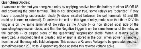
I am planning on installing an electric fan in my 99 Silverado. It will some on, triggered by the engine computer, when the engine gets to X temperature. It will also need to be on when the AC is on irregardless of the engine temp. The trigger wire coming from the engine computer provides a ground. The trigger wire for the AC will be a tap into the positive line of the compressor motor. I can figure out how to wire the relay with the trigger wire from the computer. Since it provides a ground I could just pick up an ignition switched wire from some where. These would be the 2 wires for the coil right? I'm stumped on how to work the AC wire into this since it is positive.
Replies:
Posted By: t&t tech
Date Posted: February 02, 2010 at 2:53 PM
I can think of a simple way, assuming the feed of the compressor is adequate to run the fan, wire a single pole double throw relay like this Pin 30 - The positive lead of fan (ground the negative lead of the fan) Pin 87a- To the feed of the a/c compressor pin 87- To a twelve fused source according to the fan's needs! Pin 86- True Ignition Pin 85- To the ground signal from the computer! Mr. Iidot or Mr Pierson or one of the relay guys will correct me if it isn't that simple! -------------
Posted By: kaztheminotaur
Date Posted: February 02, 2010 at 4:41 PM
Thanks. I'd rather not run the AC compressor and the fan motor off the same feed wire like that. If the feed wire could handle the current that would be the most simple though like you said
Posted By: howie ll
Date Posted: February 02, 2010 at 5:45 PM
The fan is what draws lots and lots of juice, t&t, the comp clutch, hardly anything.
Posted By: dualsport
Date Posted: February 03, 2010 at 4:36 AM
I'd just invert one of the two signals with either a relay or transistor to match the other, and drive the fan relay from the matching polarity controls.
You'd only need a small relay controlled by your fan control output from the engine computer (the smaller the better depending on how well it's capable of driving a inductive relay load. Then diode isolate the two signals, feeding to your big fan relay.
Posted By: kaztheminotaur
Date Posted: February 03, 2010 at 7:59 AM
Here is what I came up with: 
Posted By: dualsport
Date Posted: February 03, 2010 at 11:15 AM
I'd suggest not running the main fan power through both relays like that. Just use a small relay to invert the control signal and use the output from that for the main power relay. Having the fan current run through both relays that way is more failure prone since you have two relays in series, and the 87A contacts generally have lower current ratings than the 87 NO relay terminal.
Posted By: tommy...
Date Posted: February 04, 2010 at 6:55 AM
https://bcae1.com/coolfans.htm------------- M.E.C.P & First-Class
Go slow and drink lots of water...Procrastinators' Unite...Tomorrow!
Posted By: kaztheminotaur
Date Posted: February 05, 2010 at 6:17 AM
Here is relay diagram #2: 
Posted By: dualsport
Date Posted: February 05, 2010 at 6:56 AM
#2 looks good- I'd stick a diode across the fan relay coil to help protect the engine computer output. Also make sure it's okay to ground the computer output when it's not active, otherwise add an isolation diode in series with it also.
Posted By: oldspark
Date Posted: February 05, 2010 at 7:55 AM
x2!
Looks good. A nice solution.
And now even using conventional 85 & 86 polarity (relay coil).
Definitely worth the transient suppression diode across fan relay 86-85 unless the ECU output is a relay (but it's probably an Open-Collector transistor/FET output).
And #85 to ECU diode as suggested - just in case!
Posted By: kaztheminotaur
Date Posted: February 07, 2010 at 11:42 PM
What kind of diodes would I need and can I get them at Radio shack?
Posted By: howie ll
Date Posted: February 08, 2010 at 1:51 AM
1N4004, yes to Radio Shack, the band sides of the diodes go to 86 (pos. coil) and the other sides to 85 (neg. coil).
Posted By: kaztheminotaur
Date Posted: February 08, 2010 at 2:39 AM
Thanks. How would I add a diode to the engine computer trigger line to keep ground from being applied to it when it isn't activated but the A/C trigger line is?
Posted By: kaztheminotaur
Date Posted: February 08, 2010 at 2:52 AM
I see that those diodes are rated at 1 amp...that doesn't seem like very much ?
Posted By: kaztheminotaur
Date Posted: February 08, 2010 at 3:28 AM
If I used SPST relays would I still need diodes across 86 and 85 ? I'm thinking about using a large 100A industrial relay like this one from Mouser: https://www.mouser.com/ProductDetail/Stancor/120-902/?qs=sGAEpiMZZMtSzCF3XBhmW1unbvAnCJgIftLBrfiEQi8%3d I realize that is more relay than i will need but better to over build it than under build it...
Posted By: oldspark
Date Posted: February 08, 2010 at 3:44 AM
kaztheminotaur wrote:
I realize that is more relay than i will need but better to over build it than under build it...
Not when its 2/3A solenoid blows the ECU.
And not when it's big, clunky, overpriced, a fitting issue (ie hazard), etc.
Normal 30A or 15A relays will do fine, with nice spade connectors for easy replacement.
Posted By: howie ll
Date Posted: February 08, 2010 at 3:58 AM
Well answered Pete. 1 amp diodes are more than adequate for the coil draw on NORMAL relays, also use 4 pin where you can, the current ratings are higher.
Your other question, the answer is in line on the ground switch to terminal 85, band away from the relay.
Posted By: kaztheminotaur
Date Posted: February 08, 2010 at 4:47 AM
oldspark wrote:
kaztheminotaur wrote:
I realize that is more relay than i will need but better to over build it than under build it...
Not when its 2/3A solenoid blows the ECU.
And not when it's big, clunky, overpriced, a fitting issue (ie hazard), etc.
Normal 30A or 15A relays will do fine, with nice spade connectors for easy replacement.
I don't follow you on the 2/3 A solenoid blows the ECU ?
Posted By: oldspark
Date Posted: February 08, 2010 at 5:10 AM
Thanks you Howie.
Unfortunately however, I regret to inform you that YOU are WRONG!
(Bear with me readers, this is for fun - Howie is right, but shhh!)
As per some other "expert advice" forum (alas I do not know which), I hereby present the following:
(Howie - skip this line. Others - DO NOT follow the next advice - instead follow Howie's above!!
 DO NOT FOLLOW THE ADVICE IN THE ABOVE IMAGE
I originally included something like the above in my last reply, but later deleted it after I thought I got it wrong!
But I am right... amn't I... [For quenching - Kathode/line towards +ve (#86); anode to gnd/negative (#85)]
 ? ....or  &  ?
I think I'm right - never trust expert forums.
Except this one.
And Howie.
BTW - I was thinking the 1A diode was enough for the quenching.
[And yes, it should be 400V; 200V can be a bit low. Besides, the IN4004 400V/1A is now generally "the common" lowest rated diode - ie, lesser rated power diodes cost more!]
But it is also fine in series with any "normal" relay - even the oversized 100A relay with its 8W = ~0.7A solenoid/coil.
I'm even thinking of buying a bulk pack of 1N4004 (a few dollar$ for 100) and throwing out those unlabelled 50V 1A I got years ago for 2c each - 50V "unpolarised" cleanskins just ain't worth it!)
Rem: Hail Howie!!
Posted By: oldspark
Date Posted: February 08, 2010 at 5:20 AM
Sorry - I missed the update....
kaztheminotaur wrote:
I don't follow you on the 2/3 A solenoid blows the ECU ?
A typical 12V 30A relay is usually at least 60 Ohms (coil/solenoid) - ie, ~200mA (12V/60R).
That 100A relay/solenoid's coil (solenoid? ) is 8W hence ~0.67A (8W/12V).
What can the ECU sink?
I thought I read 200mA but I might be confusing threads....
But less is better.
And though ECUs may switch more, they may only be designed for a typical automotive relay.
Not that I expected that to be a clincher. Although this isn't an airconditioning or heating plant (where oversize is VERY undesirable!), and whilst I like "safe" (and reliable and economical) design, there is overkill.
And I doubt your fan(s) total 360 Watts??
Posted By: kaztheminotaur
Date Posted: February 08, 2010 at 6:39 AM
The fan I plan on using has an average amp draw of around 38 and a spike, when starting from stop to high, of around 50. So that should be 547 watts average and a spike of 720 at 14.4 volts ? Here is my 3rd. diagram with diodes added:
 < color=#0000ff size=3 face="Times New Roman"> < color=#0000ff size=3 face="Times New Roman">
Posted By: kaztheminotaur
Date Posted: February 08, 2010 at 6:42 AM
Posted By: oldspark
Date Posted: February 08, 2010 at 7:14 AM
Fair enough - my apologies.
Though I still think a smaller "typical" 60A relay is nicer - though they probably have 9mm (3/8") spade connectors for the contacts
Don't worry about Watts - relay contacts are current-Amps devices.
And remember - not much more than 8-letter image filenames.
FYI - I use a $13 60A (70A) relay to connect my 2nd battery. It is turned on by the alternator's charge lamp wire. Twice now it has handled jumpstarting my flat front battery via the 60A relay & 2x50A circuit breakers; the starter is a reduction type that normally takes ~ 120A excluding solenoid. Viz:
Posted By: kaztheminotaur
Date Posted: February 08, 2010 at 7:23 AM
I found some 70A automotive relays on the website where I am going to order the rest of my stuff from. Diagram try #3: 
Posted By: oldspark
Date Posted: February 08, 2010 at 7:29 AM
Filename fr3(?) looks ok, but maybe download to your PC first.
I could be a permissions error.
I do a Preview Post before Post Reply to ensure the image is there.
There is no error indication - you just end up with the placeholder "stamp" (square).
Ad rem - I think a 200k limit.
I cropped, shrunk & resaved the relay image above, but all were larger than the original. So more screen space, but less bytes (~16kB?).
Posted By: kaztheminotaur
Date Posted: February 08, 2010 at 7:35 AM
I cropped it down to 600 pixels wide and it is 50K in size. 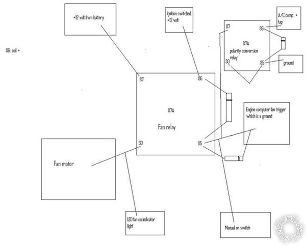
Posted By: kaztheminotaur
Date Posted: February 08, 2010 at 7:36 AM
I uploaded it to the server also...that seemed to work.
Posted By: howie ll
Date Posted: February 08, 2010 at 8:38 AM
Yes to that last diagramme, diode position is correct, wire all other leads to 85 on fan relay AFTER diode!
Posted By: dualsport
Date Posted: February 09, 2010 at 11:48 PM
oldspark wrote:
BTW - I was thinking the 1A diode was enough for the quenching.
[And yes, it should be 400V; 200V can be a bit low. Besides, the IN4004 400V/1A is now generally "the common" lowest rated diode - ie, lesser rated power diodes cost more!]
But it is also fine in series with any "normal" relay - even the oversized 100A relay with its 8W = ~0.7A solenoid/coil.
I'm even thinking of buying a bulk pack of 1N4004 (a few dollar$ for 100) and throwing out those unlabelled 50V 1A I got years ago for 2c each - 50V "unpolarised" cleanskins just ain't worth it!)
Rem: Hail Howie!!
Just a comment-
The voltage transient supression occurs in the forward biased region of the diode, so the voltage rating doesn't matter for this purpose. They'll both clamp to the same 0.7V over rail. If you're just running 12V equipment, the 1N4001 will serve just as well as the 1N4004's. It's the same 1A rating for both, so they'll be equivalent.
Posted By: oldspark
Date Posted: February 10, 2010 at 12:25 AM
Good point.
I tend to think of the "not uncommon above 200V" spikes that can occur (hence prefer next 400V rating) and think of that spike superimposed as a +ve going spike, hence exceeding rev breakdown voltage. But that may not be valid. (Ah - memories!)
I know in practice that other things are likely to absorb such +ve transients whereas even a smallish -ve voltage transients can do massive damage (say -0.3V for chips or -0.6V for most other circuits, where minus means below 0V = ground).
But usually spikes >50V are rare. (But I know 200 Amp spikes with halogen bulbs are not rare!)
Now, will a forward biased spike that exceeds the diodes PIV rating arc the diode? And ..... Ah - memories!
Posted By: dualsport
Date Posted: February 10, 2010 at 6:54 AM
Well, if it's a forward biased spike, it really can't reach the PIV, because it'll start conducting to clamp it down right away. If it's a huge current surge that has enough energy to exceed the peak current limits of the diode, then it might be trouble. But that would be exceeding the current limits, and still not related to the peak inverse voltage.
If the diode is used for AC rectification of 120V, it'll be important to make sure it can hold off the large reverse voltages. But that's somewhat rare for 12V automotive stuff.
Posted By: oldspark
Date Posted: February 10, 2010 at 7:11 AM
Ah - so you can never exceed the PIV in a forward direction? Hmmm?
(Even Hi-Z circuits & chips?)
And whilst I definitely recall 200A spikes, I only recall 200V spikes from reading, though I think I have seen 200V transients on CRO pics/dumps.
But I won't vouch that the 200V is not a misprint or misunderstanding of 200A, or based on some normalised 1-Ohm cable resistance.
But I agree that a 50V rating should be enough.
But 50V is now difficult to find here - IN4004 is the minimum.
And maybe they specify >200V in expectation of electric welding repairs LOL! (In case they isolate the batt- instead of the batt+ ....)
Posted By: kaztheminotaur
Date Posted: February 10, 2010 at 8:17 AM
OK, now you guys have lost me... 
Posted By: oldspark
Date Posted: February 10, 2010 at 10:30 AM
Don't worry - it's just banter. In my case on things I haven't looked at for ages..... and pointing out that forward biasing only clamps if there is a low-resistance path to a power rail (ie, if a coil turns on, its +ve 50V or 250V spike is likely to damage IC/chip inputs if they are unpowered (ie - not internal clamping to the +ve supply)).
Not that a relay quenching diode is forward biased in that situation...
Forget it - late night speculation....
Posted By: kaztheminotaur
Date Posted: March 29, 2010 at 10:43 PM
So the bottom picture would be the correct way to wire the diode to protect the engine computer output? 
Posted By: oldspark
Date Posted: March 30, 2010 at 2:40 AM
Not for spike suppression - you had that correct in your diagram on the last page - ie, diode between #85 & #86 with the line (Kathode) towards the more positive - namely #86 by convention.
What you have drawn in the bottom of the diagram above is that current will only flow from #85 to the ECU (the current flows out thru the line end of the diode).
Hence for the relay to switch, #86 is positive (say +5V or +12V etc) and the ECU output connect to GND to turn the relay on.
That is a very common switching method - aka GND switching or Open-Collector output. It is common because it doesn't matter if the relay is 12V & ECU 5V etc (an Open-Collector output normally handles 20V or more).
That diode doesn't do anything to protect the ECU - I think you are getting confused with the spike suppression or quenching diode between #85 & #86.
Posted By: kaztheminotaur
Date Posted: March 30, 2010 at 6:51 AM
How would it change if I reversed the diode? I want to protect the engine computer from anything that might accidentally go back up the line.
Posted By: oldspark
Date Posted: March 30, 2010 at 7:17 AM
Then it only allows the ECU to supply current to the relay.
The 85-86 reverse biased diode quenches relay-coil induced spikes in case the controlling circuit does not have it.
But if an ECU is designed to control a relay, the ECU should have that protection anyhow.
The in-line (series) diode us unlikely to protect the ECU - it will not stop over-current etc.
To be certain, you need to find out what your ECU is intending to switch, or whether it is open-collector (grounding) or supplies +ve current (of so, at +5V or +12V etc?), and what current it can source or sink.
I'm not sure if you have supplied such info... I can;t recall - Id have to reread the lot.
But do you have any reason to think the ECU cannot supply the load (relay) you intended?
(Ah - it's for a fan...)
Posted By: kaztheminotaur
Date Posted: March 30, 2010 at 7:38 AM
I guess it is open collector since it provides a ground. I have 3 different sources of a ground that will trip the relay: engine computer, a manual on switch, and the AC trigger.
Posted By: dualsport
Date Posted: March 30, 2010 at 7:50 AM
If there's any question about whether the ECU might be damaged you can add a transistor driver to buffer it. The ECU output would then only need to supply a very small current to control the relay.
Posted By: oldspark
Date Posted: March 30, 2010 at 8:21 AM
The other advantage with open-collector outputs - they can all be wired in parallel.
The manual on switch is effectively OC (Open Collector) (ie, GND, else open).
If ECUs are GND switching, then they are usually OC (like, I mean, if you are grounding, why the bother providing any power/voltage when it is NOT grounded? Make it like a simple relay - its output is connected else not).
Probably too the AC trigger if it is a single-wire switch - ie, a single-wire thermal switch... like a single wire oil-pressure switch, it can only switch to chassis/block/frame/body = GND.
By connecting all 3 together to the relay #85, you effectively have a logic-OR situation. IE - switch OR ECU or AC are connected to GND which means "fan on".
Logic OR means and-or(like English - at least now officially in Australia)- ie, any of the switch or ECU or AC can be GND, but can also be switch and ECU etc or all (three) inputs.
But won't you blow them up by paralleling?
No - that's the magic of Open Collector. Like points or ignitors for an ignition coil - you can't hurt a GND connection with another GND connection. (The IgCoil may not fire until all GNDs are "opened", but you won't wreck the points/ignitor etc if they are all closed to GND, or not.)
Think of 3 GND switches to turn on a "hot" bulb (ie, other bulb end connected to +12VDC, 120VAC etc).
So what if switch(es) 1, 2 or 3 are on in parallel?
Different maybe if connecting 3 hot switches to a grounded bulb. We might then connect 1 to 2 to 3 hence interconnect power sources (+12V & +13.8V etc) or different 110VAC phases, or differently powered loads together....
Apols for the ramble... I should find that neat logic-equivalence diagram I saw somewhere.....
Is that reasonably clear?
An OC is like ignition points etc - it is either connected/shorted to GND, else not (and NOT means "floating" - a hi-impedance to any voltage etc).
OC may be a switch to GND (else open - like ignition points), or a transistor - specifically an NPN transistor being either "ON" to GND else off & floating.
Its Emitter is connected to GND and its Collector is its output.
When the transistor is on, its output (Collector) is connected to its Emitter = GND.
When off, the Collector is floating. It is not connected to GND/Emitter - that is now an Open circuit - hence the name "Open Collector" - it is open unless connected to the Emitter which is GND.
Alas though OC is a brilliant system, I suspect my explanation is not. (That's Haemo's fault - I've hit the wine again!)
Posted By: kaztheminotaur
Date Posted: March 30, 2010 at 8:55 AM
I think I am following...slowly HAHA :) So if the engine computer ground trigger is OC that means that it isn't connected to anything when not "active". If so then I don't need a diode since it isn't connected to anything when "not active"
Posted By: oldspark
Date Posted: March 30, 2010 at 9:20 AM
Bingo!
End of story...
But to confirm... (Oh no - here we go again. Aka BOHICA)
If Open-Collector output....
When "off", the output merely floats. In practice it will tolerate whatever the "Collector-Emitter breakdown voltage" is, but this is usually above 30V so that even if our 12V systems hit 16V or 20V - no problem!
And when on, it shorts (connects) to GND. It will tolerate whatever the output can "sink" to GND. (Source current if supplying power (voltage/current) to a load.)
Although computer chips (CPU etc) might only sink or source 1mA or 20mA, an ECU should (or will!?!) have a buffer to source/sink more.
Somewhere should state what they are capable of.
But ECU outputs intended to drive relays should expect to drive (IMO) at least 200 Ohm relays (coils/solenoids) - though probably down to (say) 60-Ohms for automotive relays. (That's ~70mA (200R) or 250mA for 60R; where R=Ohms.)
Great to see that following slowly reaps its rewards.
Though I'm sorry if it's poor comms that makes it slow....
But slow is relative.... It's taken me years - how long's it taken you? (LOL - it's not a race! But I do know a lot of very fast idiots! Let's just say they burn out. LOL - get it, burn-out - unprotected over-current and no tomorrow... FIGJAM!)
Yes dear, I'm coming to bed.... I'll just empty my bag....
Posted By: kaztheminotaur
Date Posted: March 30, 2010 at 9:27 AM
Bedtime? It is the middle of the day here! I've been tinkering in 12V stuff for a while now. I did catch a car on fire once so I am very careful nowadays. I've had remote control cars off and on for years. With the new LiPo batteries and brushless motors you can really put down some awesome power. I'm slowly realizing that the key to efficient power is running a low RPM per volt motor (750 in my case) on higher voltage (10S LiPo) runs cooler than the other way around.
Posted By: oldspark
Date Posted: March 30, 2010 at 9:51 AM
It's (hic *) 01:40 hic... here..
Yeah - I was introduced to LiPos by a Z-900 racing mate running a full-loss CDI ignition (and having the young-uns on their whatever newbies think wth?!)
He explained their flexibility (literally - mold them around your seat or frame etc) and their energy density & delivery.
Later I saw how greenhouse-gassing model aeroplanes had become electric engined prop & jet craft with 300-400A motors! (Alas no less greenhouse gasses here - we don't have nukes. But some assure us (morons?) that we can have "clean coal". rotflmfho..)
As to low RPMs....
If its alternator output, it needs to match your normal RPMs (hence racers tend to gear down).
If it's knowledgeable people like me that realise it's all about toque (and not power), then that suggests low RPM too (I loved beating hot cars & V8s with my 4 cylinders chugging along at 2,000 - 3,000 RPM. It made me think of "The World's Fastest Indian" - wasn't that at 4,000 RPM?).
But yeah, speed isn't everything.
And she agrees.
Or to paraphrase earlier - slow is cool, and effective. (Not hot.)
Posted By: kaztheminotaur
Date Posted: March 30, 2010 at 8:46 PM
How would I wire up a 3 position switch to off, on, and auto. I would need a DPDT right? Auto would be silent, on would make a ground, and off would break a ground. The grounds in question would be connected to 85 on the fan relay.
Posted By: oldspark
Date Posted: March 31, 2010 at 3:31 AM
Posted By: kaztheminotaur
Date Posted: March 31, 2010 at 6:30 AM
Might I impose on you to draw that using the 6 pins on the back of the switch and not the scientific diagram symbols?
Posted By: oldspark
Date Posted: March 31, 2010 at 6:46 AM
There's no might about it... (lol).
You draw the back of the switch & I'll add the rest.
Posted By: kaztheminotaur
Date Posted: March 31, 2010 at 7:34 AM
I don't think I can do this with a DPDT switch. I need (2) SPST switches. 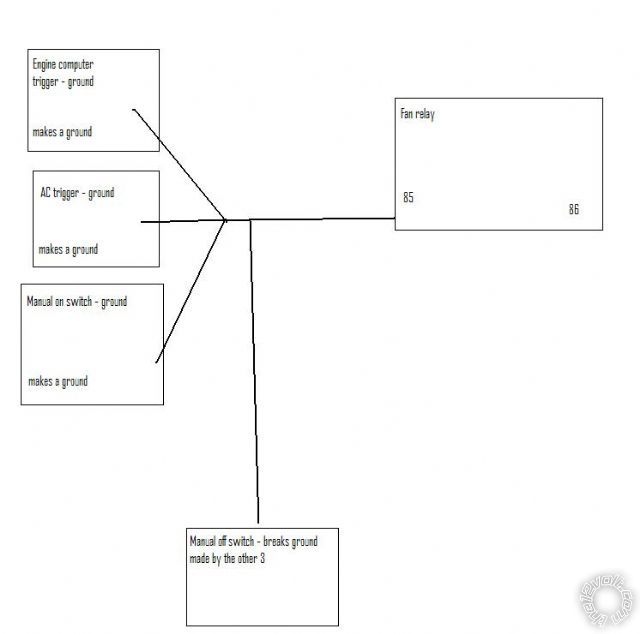
Posted By: oldspark
Date Posted: March 31, 2010 at 8:14 AM
What you were describing is a SP3T switch - ie, single pole, 3 position (normally with center off).
IE: auto - off - on
Posted By: kaztheminotaur
Date Posted: March 31, 2010 at 9:29 AM
Those seem kind of hard to find...one that meets my needs anyway. I checked mouser.com I think it will be easier to use 2 SPST switches
Posted By: howie ll
Date Posted: March 31, 2010 at 9:34 AM
Surely a single SPDT centre off switch is all that's required?
Howard a sub-contractor and by the way Oldie you should see this post before the spell-check! Me fingers is too big for the bloody keyboard!
Posted By: kaztheminotaur
Date Posted: March 31, 2010 at 10:06 AM
I don't think that will work because the at rest position of the on switch needs to be open and the at rest position of the off switch needs to be closed. Bah... I was thinking about this at work last night. I'm sure there is a simple solution to this that I'm not getting... 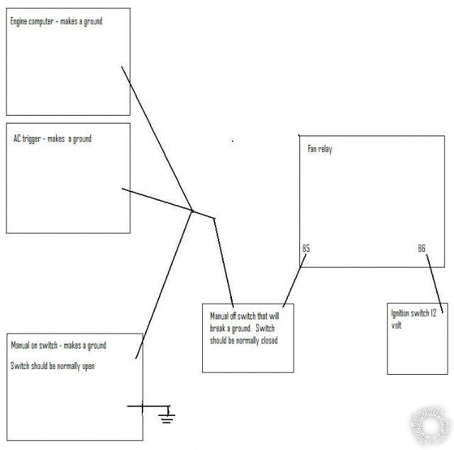
Posted By: kaztheminotaur
Date Posted: March 31, 2010 at 10:11 AM
Both switches will have to be able to be closed at the same time for the maual on to work, However the manual off will work regardless of the position of the on switch.
Posted By: kaztheminotaur
Date Posted: April 10, 2010 at 5:43 AM
Today is the big day for the electric fan install. This past week I have been running all the wiring for the fan. I have the relays all wired up and ready to put in. Last night I took out the belt driven fan.
Posted By: kaztheminotaur
Date Posted: April 10, 2010 at 8:14 PM
Well I got everything installed. I need a diode on the fan because, at 30 mph., the fan makes enough current to make the LED light dimly.
|
