5V Trigger for 12V Relay
Printed From: the12volt.com
Forum Name: Relays
Forum Discription: Relay Diagrams, SPDT Relays, SPST Relays, DPDT Relays, Latching Relays, etc.
URL: https://www.the12volt.com/installbay/forum_posts.asp?tid=120010
Printed Date: April 17, 2026 at 6:23 AM
Topic: 5V Trigger for 12V Relay
Posted By: jaspershotrods
Subject: 5V Trigger for 12V Relay
Date Posted: February 09, 2010 at 7:43 PM
i need to know if there is a way to trigger a 12v spst relay using 5 v the switch im using cuts the volts more than half. thanks
Replies:
Posted By: i am an idiot
Date Posted: February 09, 2010 at 8:03 PM
Is it a lighted switch. There is no other reason for the voltage being cut down by the switch other than you having it wired through the lamp in the switch.
Posted By: KPierson
Date Posted: February 09, 2010 at 9:36 PM
Yeah, the switch shouldn't do that. But, to answer your question there are two routes you could take - a 5vdc relay with the contacts wired to the coil of the 12vdc relay or use a npn transistor (base - 5vdc switched input, emitter to ground, collector to (-) side of coil of 12vdc relay) ------------- Kevin Pierson
Posted By: oldspark
Date Posted: February 09, 2010 at 9:54 PM
I agree with the above.
Usually it's a 5V circuit to switch a 12V relay. That's easily done by ground switching (assuming their 0V aka grounds are common).
[ FYI: That's the common technique used for many modules and circuits - ie an input out output low or ground is the "active" state. EG - Kettering and electronic ignitions, computers (internally between chips).
Also called or akin to "Open Collector Outputs".
But not common in "powering" scenarios as on vehicles - ie - (except for horns and some lighting systems) most switch power to the load - ie, switch the +12V, not ground the load (but the controlling signal may well be a ground - eg ECU, alarm, etc). ]
Posted By: howie ll
Date Posted: February 10, 2010 at 5:29 AM
Or using a "normal" 12v+ switch where the illumination is in parallel, I've never seen one that didn't output 12volts!
Posted By: oldspark
Date Posted: February 10, 2010 at 6:57 AM
Oh Howie!
You silly-billy - it's obviously a 7V bulb! (Must be French). 
I assumed that our clever Idiot is correct - the 5V being measured with a load connected to the lamp's grounding terminal or similar.
Jasper may have to clarify his description.
[ FYI - If it's a 12V bulb-illuminated switch off 12V, then it will be 12V if on, else off and hence "floating" else 0V (gnd) if connected to a load.
The bulb is connected between output (internally) and a terminal that you connect to GND.
Usually GND is the middle terminal with the +12V in and switch output at the ends. ]
If it's a 12V or other illuminated switch connected to a 5V supply, then yes, it will be switching 5V (with a dull bulb).
Otherwise it is connected wrong, or a faulty switch, or....???
Posted By: jaspershotrods
Date Posted: February 10, 2010 at 11:49 AM
it is a flat pannel switch and with 12.5 in and the switch closed it has 4.8 coming out so it will not acctivate a 12 v spst relay just wondering if there is a relay i could use that would trigger off of less than 5 volt but still let 12 v through to the load (window motors)
Posted By: jaspershotrods
Date Posted: February 10, 2010 at 1:08 PM
i can only get about 66ma through the switch and need 130 ish to trigger a relay thanks again
Posted By: KPierson
Date Posted: February 10, 2010 at 1:46 PM
How many pins does the switch have? It still sounds like you are running the load through the lightbulb instead of around it. Try this - with the load completely disconnected, but the power in and ground still connected, does the light still light up in the switch? ------------- Kevin Pierson
Posted By: jaspershotrods
Date Posted: February 10, 2010 at 3:35 PM
there is no light it is a flat pannel switch 1 common 4 out puts i cant get any more than 66ma to come thru can i use a transistor to up the output and if so what am i looking for thanks i also tried to use the common on switch as - trigger wont trip relay that way either
Posted By: oldspark
Date Posted: February 10, 2010 at 4:07 PM
 Some Idiot introduced the bulb possibility - and I've been stuck on it since. (Some people never listen. Nor read.)
I reckon replace the switch unless you are sure that is normal behavior - otherwise it seems to be failing.
Do you have specs on it, or a model number etc?
It sounds like it has over 60 Ohms resistance!
Posted By: jaspershotrods
Date Posted: February 10, 2010 at 6:07 PM
103.5 ohms tried two brand new same thing
Posted By: oldspark
Date Posted: February 10, 2010 at 7:03 PM
In that case, yes - a transistor or FET etc.
Any preference?
The simplest is an N-device (NPN transistor or N-channel FET etc) that grounds the relay when the switch is on (+ve).
A pity it wasn't stated earlier - it's not a "voltage" switch(ing), it's a series resistance.
Posted By: i am an idiot
Date Posted: February 10, 2010 at 7:10 PM
Did you purchase the switch online? If so do you have a link to the product?
Posted By: i am an idiot
Date Posted: February 10, 2010 at 9:18 PM
Was the switch designed to power LEDs? It sounds to me that there are 100 ohm resistors internal of the switch.
Posted By: jaspershotrods
Date Posted: February 11, 2010 at 12:48 AM
 pilot makes the setup all i used is the pressure switch and i can use it to trigger -or+ doesnt matter to me send power by +trigger to relay or send power by switching ground on relay im ok with wiring just not sure about npn transistors or how they work i found a prouduct from (pie) called cyclops that in basic basic form is a relay that will switch with very low ac or dc or audio nice stuff but kind of bulky pilot makes the setup all i used is the pressure switch and i can use it to trigger -or+ doesnt matter to me send power by +trigger to relay or send power by switching ground on relay im ok with wiring just not sure about npn transistors or how they work i found a prouduct from (pie) called cyclops that in basic basic form is a relay that will switch with very low ac or dc or audio nice stuff but kind of bulky
if i could up the amps comming out of the switch (66ma) to (140ma) i could use a spst 12v relay on this setup what type of transistor specs ect would i be looking for and will it increase volts and amp thanks again
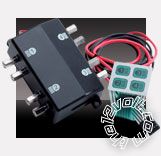
Posted By: jaspershotrods
Date Posted: February 11, 2010 at 12:55 AM
 sorry about the pic not to good wit posting sorry about the pic not to good wit posting
thanks
Posted By: oldspark
Date Posted: February 11, 2010 at 1:57 AM
Not sure what is going wrong there!!!!

What do you want to switch?
[Is it still window motors? If so, do you know the circuit required - ie, 2 relays per window? And what Amperage is the motor?]
I'm thinking why use a transistor & a relay if a transistor else FET alone will do it?
I'd also like to ask ytf use that switch....???!!
Posted By: i am an idiot
Date Posted: February 11, 2010 at 4:02 AM
Take the cover off of the box and look for resistors.
Posted By: KPierson
Date Posted: February 11, 2010 at 5:34 AM
I would just get a 5vdc reed relay. The contacts won't switch quite as much, but they will switch 12vdc. Reed relays use extremely low current and you can get them with 5vdc coils. ------------- Kevin Pierson
Posted By: jaspershotrods
Date Posted: February 11, 2010 at 12:17 PM
the reason for the switxh is it will hide in the center console of custom 68 camaro im building for a customer i will try to get pics up and yes it is to relays per window im not sure how to do it any other way if the switch and tranistor will work that would be great because i dont have a lot of room left thanks for beeing patient
Posted By: oldspark
Date Posted: February 11, 2010 at 10:02 PM
Dang! I found a FET circuit I drew, but it was a P-channel....
All you need is one FET per circuit - ie, instead of the relay.
FETs that switch 10A - 50A or more are commonly available and sometimes cheaper than relays. (I can get ~60A MOSFETs for $2 each.)
So powering a window motor is no problem.
The other main component needed is a resistor to protect the FET's "Gate" (equivalent to the Base of a transistor, or coil on a relay), but you have that as part of your switch.
[FYI: For transistors, the Base current determines output current so the Base resistor is critical. But FETs are a high impedance VOLTAGE input so its input resistance is NOT critical - only the Gate voltage is.]
And to ensure the FET turns off, a resistor from Gate to ground - in your case probably 1k (1,000 Ohms) or above.
So one resistor and one FET instead of (resistors? &) a transitor and a relay?
And silent operation?
And more than (say) 100,000 relay operations?
The rest is implementation.
I'd assume the FETs will NOT be in the console.
Relays when used are usually in the doors etc so that only one pair of heavy wires are needed (+12V & gnd).
The same would apply to the FETs.
But the FETs might require a small capacitor or something to filter out any noise from the console to the FET gate. Then again, a FET Gate may need a few volts to turn on.... What voltages can internal transmitters, GSMs, audio and switching produce in "other" wires?
Just find a nice cheap local N-Channel MOSFET that handles the motors (ie - max current - eg, when jammed etc), but consider the biggies like 50A - they are still much smaller than relays.
We can take it from there if interested....
(Dang! Another drawing....)
Posted By: howie ll
Date Posted: February 12, 2010 at 4:41 PM
This is all running around in circles! The quick cheap and effective answer (no relays required) would be to get some illuminated Spal switches!
Posted By: oldspark
Date Posted: February 12, 2010 at 5:59 PM
Yes Howie, but the customer....
lol - But I agree. However if people are keen to match the normally incompatible....
(At least this isn't like after market 2nd hand EFI/ECUs where people buy some ECU configuration and rather than pay for a re-config, modify their hardware (ie, distributor or sensors) at often greater expense only to end up with unique hardware!)
The bummer here was the time to realise it's a series-resistor switch. That was the circling!
I reckon that switch is perfect for FETs which are cheaper, smaller, quieter and last longer than relays, and can almost be used directly with no other components - maybe not even the turn-off resistor.
But FET and relay, or worse still - transistor with relay (though without may not be too bad).... not me.
Posted By: i am an idiot
Date Posted: February 13, 2010 at 7:43 AM
https://www.the12volt.com/installbay/forum_posts.asp~TID~120010~PN~0~TPN~2#588006 If you find the resistors, you may be able to short them and then use it as a regular switch.
Posted By: KPierson
Date Posted: February 13, 2010 at 9:15 AM
It sounds to me like he is just using the switches, he isn't using the actual box. That would mean the resistors are inside the switch and that switch doesn't look very serviceable. Just use a transistor, FET, or reed relay - you have multiple options and they will all work! ------------- Kevin Pierson
|