wiring needed, boot popper kit
Printed From: the12volt.com
Forum Name: Relays
Forum Discription: Relay Diagrams, SPDT Relays, SPST Relays, DPDT Relays, Latching Relays, etc.
URL: https://www.the12volt.com/installbay/forum_posts.asp?tid=120159
Printed Date: March 13, 2026 at 10:41 PM
Topic: wiring needed, boot popper kit
Posted By: esa
Subject: wiring needed, boot popper kit
Date Posted: February 16, 2010 at 1:30 AM
Hi
I am trying to wire a boot popper kit to my car with a slight twist I want to be able to pop the boot either from pressing the button that is mounted in the dash or the button that will go where the rear wiper used to be. I will be using the rear wiper motor as my power supply. My questions are the following,
Can I use two power sauces ( i need to be able to press either switch and it should open the boot) going into pin 86 if not what options have I got?
Is it ok to wire one device to more than one relay ? ie the boot popper slenoid because if it is then I suppose I could use two relays and that should work.
Regards
Olumbe
:peace:
Replies:
Posted By: oldspark
Date Posted: February 16, 2010 at 3:49 AM
So you no longer have the rear wiper and motor(?).
Rather than one device to 2 relays, it's better with one relay triggered from 2 source (switches).
The 2 sources are wired to the relay via diodes (eg 1N4001 or 1N4004 etc) to prevent one switch feeding the other.
If (also) using two power sources - I'd question the logic of doing that - but you would similarly connect the two sources together via two diodes, but in this case, each diode MUST handle the current of the load (popper/solenoid) - ie, 3A, 5A whatever (with 50V PIV rating or higher) eg - a 50V 3A diode, or 400V 3A diode etc.
But you are probably better with ONE source - ie, a fused source from the battery. The way the switches are powered determine the "power logic" (ie, whether IGN is on or off etc).
Does that make sense?
If not, can you draw what you want, else explain when you want the popper to operate AND when the wiper motor is powered, and its switch is powered, and the other switch you refer to?
Posted By: t&t tech
Date Posted: February 16, 2010 at 8:31 AM
Also, do not make multiple threads about the same subject! -------------
Posted By: esa
Date Posted: February 16, 2010 at 8:55 AM
sorry about the multiple threads it was an accident
Posted By: t&t tech
Date Posted: February 16, 2010 at 11:41 AM
No probs! Just letting you know!
-------------
Posted By: esa
Date Posted: February 16, 2010 at 12:08 PM
Yes the rear wiper arm has been removed. I have a smoothed tailgate that I will be putting on the car so there will be no button to open the boot. So I will be adding a bootpopper
The boot will be opened by the switch button I will mount in the dashboard but what I would also like to have is another push button switch mounted in the hole where the rear wiper used to be.
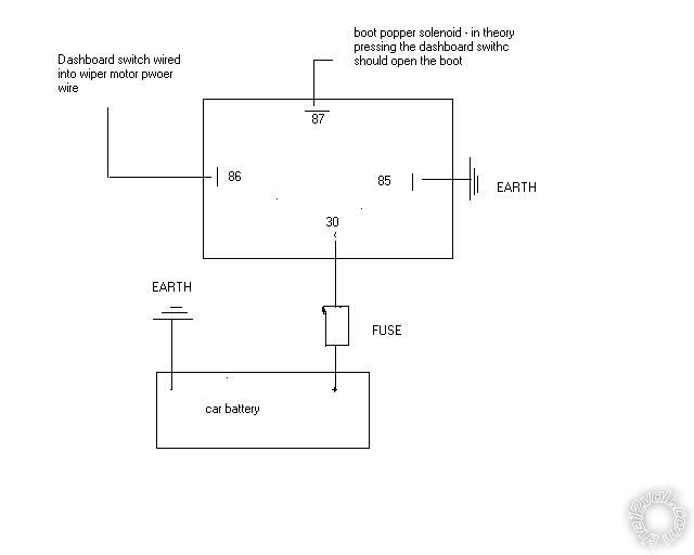
If I was just installing one push button it would be easy enough I would use the diagram below. Power from positive on rear wiper motor to a dashboard switch and to relay then to popper. Negative to relay and then to popper.
This way it only works in position 2 on the ignition.
connected to the boot popper solenoid
*
*
*
***************************************
* * *
* **** *
* 87 *
* * *
dashboard switch ****************** * * 86 85 * *********** Ground
press switch activate popper * * *
boot opens only works * 30 *
when key in IGN * * *
* * *
***************************************
*
*
*
*
*
Ground *******
* * * Fuse
**** *
***** *******
* *
* *
************************
* - + *
* Car Battery *
* *
************************
Power from positive on the boot light to switch mounted in rear wiper hole and to relay then to popper. Negative to relay and then to popper.
This works as long as the car is unlocked .
connected to the boot popper solenoid
*
*
*
***************************************
* * *
* **** *
* 87 *
* * *
rear wiper switch ****************** * * 86 85 * *********** Ground
press switch activate popper * * *
boot opens without key * 30 *
in IGN * * *
* * *
***************************************
*
*
*
*
*
Ground *******
* * * Fuse
**** *
***** *******
* *
* *
************************
* - + *
* Car Battery *
* *
************************
Posted By: esa
Date Posted: February 16, 2010 at 12:09 PM
ignore last update I'll have to redo the diagram in visio at work. Don't know how to do it in ubuntu
Posted By: esa
Date Posted: February 16, 2010 at 12:09 PM
ignore last update I'll have to redo the diagram in visio at work. Don't know how to do it in ubuntu
Posted By: esa
Date Posted: February 16, 2010 at 3:31 PM
Yes the rear wiper arm has been removed. I have a smoothed tailgate that I will be putting on the car so there will be no button to open the boot. So I will be adding a bootpopper
The boot will be opened by the switch button I will mount in the dashboard but what I would also like to have is another push button switch mounted in the hole where the rear wiper used to be.
If I was just installing one push button it would be easy enough I would use the diagram below. Power from positive on rear wiper motor to a dashboard switch and to relay then to popper. Negative to relay and then to popper.
This way it only works in position 2 on the ignition.
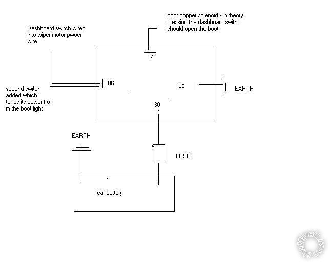
But I also want to add a second push switch can I just connect the second switch to point 86 like this
Power from positive on the boot light to switch mounted in rear wiper hole and to relay then to popper. Negative to relay and then to popper.
This works as long as the car is unlocked .
Posted By: oldspark
Date Posted: February 16, 2010 at 3:46 PM
POST EDIT - this was posted BEFORE I saw your diagram. (??!)
Your fig is fine EXCEPT that you need to insert a diode in each of wires to 86.
Schematically, the diodes "point towards" 86 this means the arrow head in its -->|-- type symbol points to 86; the arrow showing which direction current flows.
In practice, this means the band on the diode is towards 86 (just as in its symbol).
Clear?
The diodes need only be rated to carry the relay solenoid's current, and withstand automotive 16V plus any solenoid transients.
Usually 1N4004 400V/1A diodes are used - these being a very common hence cheap diode. But others should be fine too - like 1N4001 (50V/1A) etc (though I prefer at least 200V for automotive).
FYI:
You could also place a reverse-biased diode from 85 to 86 (ie arrow pointing & band towards the +ve solenoid/coil terminal from its -ve (gnd) terminal.
This is to quench -ve transients caused by coil switching. (The coil reacts to switching with an opposing spike - hence making gnd more +ve than the +ve supply. The diode hence "shorts out" the +ve gnd spike to +12V, hence keeping it below ~12V. It's the same coil principle that caused an ignition coil to spark.)
The original reply follows....it's no longer valid....
So the rear wiper has constant power.
Hence you connect that as your power input #30 with #87 to the popper solenoid.
Both switches connect via diodes to relay #86 with #85 to ground.
The rear switch is IGN powered.
The front switch is battery powered (via some fuse).
That's the simplest method.
Posted By: howie ll
Date Posted: February 16, 2010 at 5:16 PM
Can someone tell me what's the point of two buttons for the same function within a few feet of each other? And don't take the wiper source as your power you'll probably blow the fuse.
Posted By: howie ll
Date Posted: February 16, 2010 at 5:20 PM
I'm awfully sorry, I jumped in with all guns blazing only having seen half the posts, scratch my previous post!
|