light relays
Printed From: the12volt.com
Forum Name: Relays
Forum Discription: Relay Diagrams, SPDT Relays, SPST Relays, DPDT Relays, Latching Relays, etc.
URL: https://www.the12volt.com/installbay/forum_posts.asp?tid=120489
Printed Date: May 13, 2026 at 5:05 AM
Topic: light relays
Posted By: dlowry79
Subject: light relays
Date Posted: March 03, 2010 at 6:55 PM
Hi I'm wiring 3 lights to my boat - anchor light, port light and starboard light. I need the anchor light to go on when switch 1 is turned on and I need all three lights to turn on when switch 2 is turned on. The way I thought this could be done is with a relay. I've attached a basic drawing of how I plan to wire it up - the switches are fused switches, therefore I haven't drawn fuses into the diagram. Just want to get a few opinions on whether this is the best way to go before I start and whether I've drawn this up correctly and it will actually work (I have only basic knowledge of electrical 12v wiring). Thanks in advance. 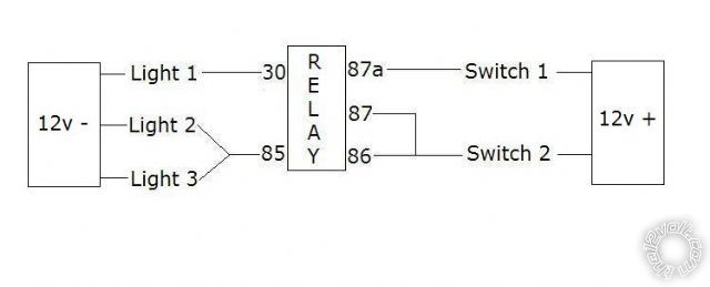
Replies:
Posted By: oldspark
Date Posted: March 03, 2010 at 9:28 PM
No. Light 2&3 will never come on (unless they are similar or lower power to the relay solenoid).
Use diodes.
+12V to each switch.
Switch #1 (through optional diode) to Anchor light.
Switch #2 to P&S lights and through diode to to Anchor light.
The optional diode for Switch#1 is to prevent Switch#2 power to the Anchor light going back through Switch#1 to the source, though that's not a problem if the source is the same battery.
The diode from Switch#2 to the Anchor light stops Switch#1 power from powering the other lights.
A diode has a symbol like (A)--->|---(K)
... where current flows from the +ve Anode (A) end through the "arrow" to the Cathode (K) end.
Just remember that the symbol's "arrow head" points in the direction of current flow.
The painted line on a real diode is its (negative or) Cathode end.
That is easily remembered by Kathode where the K is made up of an arrowhead < and the line | (so if it's ---K--- = ---|<-- ...it means current flowing from right to left).
Diodes block current in the reverse direction.
Hence in the original (A)--->|---(K) symbol, current from the right (K) towards the left (A) hits the brick wall - aka the back of the K and stops.
Te diode must be rated for the voltage involved (ie, 12V?) and the current.
In this case, the current is whatever the Anchor light uses.
EG: P=VI, so if 3W & 12V, I = 3W/12V = 0.25A.
If 24W, then 24W/12V = 2A etc.
In practice, power diodes are usually above 50V and 1A.
Very common is a IN4004 (400V, 1A) which would handle up to 10W (10/12 ~0.8A), else IN4001, 2 or 3.
Also common is the 1N5404 (400V, 3A) - ie, for the 24W light (or say up to 12Vx3A = 36W, or 24Vx3A = 72W for 24V etc).
If the lights are higher current, then replace the Anchor light in my above explanation with a relay (ie, #86).
The relay's power source needs to be fused from the battery (Batt +12V thru fuse to #30) with #87 to the real Anchor light.
The grounds of the lights (and #85 of the relay if used) are connected to ground = battery- (negative terminal = 0V, though commonly but incorrectly referred to as -12V).
Simple enough?
Posted By: dlowry79
Date Posted: March 03, 2010 at 10:04 PM
Thanks for that...I should have gone with my first thought which was using diodes. A had a spare relay laying around, hence why I thought about using a relay - that and I haven't used diodes in anything before. My new diagram now looks like this 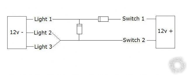
Although I'm only using one battery, I'll take your advice and use a second diode on switch 1 incase I switch to dual batteries later on down the track. Thanks you you're advice...saved me a bit of work wiring up a relay only to find out it doesn't work Cheers
Posted By: oldspark
Date Posted: March 03, 2010 at 11:27 PM
That looks better!
And it confirms that your LHS "12V-" is "ground" - the top diagram was a bit confusing (normally just a ground symbol or line etc is used, not another "negative battery" or "another half of a battery" etc. (Don't change it - it's fine! But I rarely use "physical" diagrams - I find them difficult to "understand" - mine are more schematic or circuit.)
I think I know what you were trying to do with the relay, and maybe it can work, but I figure:
- marine environment - why risk mechanical seizure etc?
- the extra relay solenoid current drain. It may be trivial, but might be 2W or comparable to an additional light...
The diodes add no extra drain - in fact they reduce current consumption a bit (but only by about 5-10% for the Anchor lamp).
And diodes do not seize. They may short or open, but it's easy jumper them if needed (easier than reconnecting a relay).
Just size the diodes for the correct current.
As long as they exceed the lamp values (A 12V 10W = 0.9A lamp might be safer with a 3A IN5404 than a 1A IN4004, but a huge oversized 1000V 50A diode will also work (but mount it centrally so the boat doesn't capsize lol).
If 5W bulbs or less, then can use IN4004 etc without problems.
And buy a few extra - the gas getting there will cost more - they can be used as spares, for the next project, or to suppress spikes from your (still unused) relay solenoid.
|