using relay to power up high beam
Printed From: the12volt.com
Forum Name: Relays
Forum Discription: Relay Diagrams, SPDT Relays, SPST Relays, DPDT Relays, Latching Relays, etc.
URL: https://www.the12volt.com/installbay/forum_posts.asp?tid=121040
Printed Date: May 12, 2026 at 2:09 PM
Topic: using relay to power up high beam
Posted By: ef yu
Subject: using relay to power up high beam
Date Posted: March 29, 2010 at 12:56 AM
well lets start from the top
car:89 crx
problem: i recently converted my old head lamps to different ones.
my original head lamps used two light bulbs(9006 & 9005). one for low beam and one for high. once the low beam are on, turning on the high beam causes the low beam to stay on with the high beam.
Now since i have changed my headlamps, it uses one bulb with dual filaments to have a low/high beam output from one bulb(h4). In this case, once the low beam are on, turning on the high beam will cause the low beam to turn off and switch on to high beam.
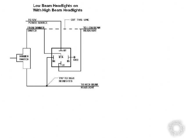
now how do i wire it up correctly? i have thought out my plan using a relay to make things work but i am a bit scared to test it as i do not want anything to go wrong. please let me know if it looks about right or needs something. heres my diagram.

Replies:
Posted By: howie ll
Date Posted: March 29, 2010 at 2:14 AM
Terminal 30 should be fused at 15 amps for running the two H4 bulbs, other wise it's quite correct.
Posted By: howie ll
Date Posted: March 29, 2010 at 2:21 AM
Sorry this is correct.
Cut the low beam feed near the relay,,
High beam signal to 86,
Ground to 85,
15amp fused to 87,
Low beam from switch to 87a,
Relay out put to lights from 30.
It's about 30 years since I did this trick!
Posted By: ef yu
Date Posted: March 29, 2010 at 2:53 AM
when reading your post, i got a bit confused.
heres what i saw when i tried to comprehend what you are trying to say.

Posted By: oldspark
Date Posted: March 29, 2010 at 3:19 AM
FYI: I've gone the other way - from hi/lo dual to dedicated lo.
Assuming the hi/lo selector to be a 2 way selector switch after the beam power switch, that merely required:
(1) moving the low beam output to the beam output (ie, before the selector switch so that low beam is always on with beams on);
(2) - if lo is to flash with hi, a diode from hi to low (eg a 1Amp diode from hi beam switched power or solenoid to the lo beam solenoid.
Doing this the other way as you require could be done by moving the low beam signal to the other side of the hi/lo selector switch (the non-hi side) assuming that side is switched.
FU, your original fig is fine where #30 is the Beam power - ie, a switch or relay that provides fused +12V to the hi/lo changeover relay.
(Strictly speaking, #85 & #86 should be swapped but only if the relay incorporates a spike quenching diode else for convention sake - #86 is the more +ve of the #85 & #86 connection).
I prefer two normal SPST relays to be used - namely one for hi & one for low where their #30s are fused +12V (from the alternator else battery) where the changeover selector switch chooses whichever relay is to be powered.
Hence if one relay fails, the other beam still works (and the relays could be swapped).
In the changeover relay version, a failed relay may mean no beams whatsoever.
Posted By: ef yu
Date Posted: March 29, 2010 at 3:41 AM
Thanks a lot oldspark.
so just to make sure, i created a final(hopefully) figure.
it shows the relay being turned on / off

Posted By: oldspark
Date Posted: March 29, 2010 at 8:19 AM
Spot on.
The lower diagram is normally the one that would be used (ie - "normal" condition meaning de-energised of off etc). From that the top diagram is easily deduced in one's mind - except when inexperienced, or experienced but not thinking correctly (lol!)
Here are a colleague's diagrams that cover what I've discussed...
All circuits use 2 relays.
The first shows a changeover relay being used for the hi-lo selection. IMO this is unreliable (meaning no redundancy - a single failure can mean no lights).
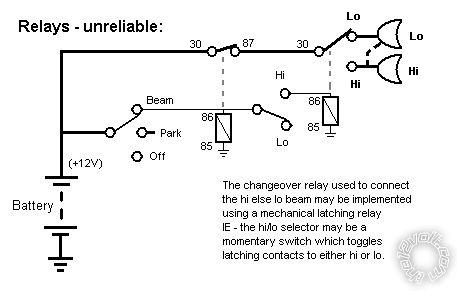
The next shows the above using identical SPST relays that could be swapped if it's the most desireable beam that fails (ie, usually low beam - replace failed lo-beam relay with the hi-beam's).
Also failure of one relay does no effect the other beam.
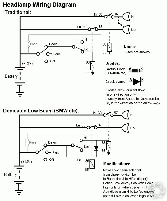
It shows the TWO topologies for a 4-headlight system - namely dedicated lo-beam or combined hi&lo-beam for one pair (and dedicated hi-beam for the other pair).
The upper "Traditional" depicts H4 type hi-lo bulbs and the dashed line between lo & hi means the hi-beam power (for the hi in the "Lo" which should probably be called outer or upper beams). (It can also take me a while to decipher his diagrams!)
The lower is the (modern) equivalent where the beams are a dedicated lo-beam, ie, a single filament bulb etc. They remain on when the hi-beam is on. (This does not occur in dual-filament bulbs like H4 as they would overheat, though they may both light in "flash" (passing) mode...)
Hopefully you'll see how the "unreliable" wiring to the RHS of the first relay (RHS of #87) is the same as your last diagram.
The first relay is merely the "beam" power - that relay is on whenever "beam" is selected, though it could be a hi-current switch (though in that case, the hi-low is probably also a switch since it's bad design to use a high-current switch followed by relays; though I have seen that used in some vehicles!)
Posted By: ef yu
Date Posted: March 29, 2010 at 10:01 AM
Oldspark, thank you very much. Appreciate the awesome helpfulness you gave me.
i do see how unreliable my way is. unfortunately, my car is already "dedicated low beam" style. and for me to use a dual filament bulb would work if i some how remove that diode that connects the hi to lo beam. but i do not know where or how to remove it. so my only way would be to modify the direction of the low beam from using the high beam as a switch instead.

Posted By: ef yu
Date Posted: March 29, 2010 at 2:48 PM
ok some one just inform me to wire straight directly to high beam. everything would work like normal. low beam are on, once the high beam turns on it should work normally, the relay would interrupt the low beam and look for a new source.
i made, hopefully my last, diagram. let me know if it should work fine

Posted By: ef yu
Date Posted: March 29, 2010 at 3:30 PM
heres how they would work.

is this a good idea?
Posted By: eljefecito
Date Posted: March 30, 2010 at 12:29 PM
Posted By: oldspark
Date Posted: March 30, 2010 at 6:35 PM
Yes!
The plot is that the hi-beam must cut power to the lo-beam.
Hence lo-beam (power) is normally connected thru the NC = 87a terminal, EXCEPT when hi-beam is powered.
The power input to 87a is the normal lo-beam power.
|