Overdrive Relay Wiring
Printed From: the12volt.com
Forum Name: Relays
Forum Discription: Relay Diagrams, SPDT Relays, SPST Relays, DPDT Relays, Latching Relays, etc.
URL: https://www.the12volt.com/installbay/forum_posts.asp?tid=121147
Printed Date: May 12, 2026 at 9:38 AM
Topic: Overdrive Relay Wiring
Posted By: akuhead
Subject: Overdrive Relay Wiring
Date Posted: April 04, 2010 at 1:00 AM
Hello. Please let me apologize in advance if this has been covered before, but I looked and looked thru the search function and didn't find anything applicable to my situation. I am installing an overdrive (Gear Vendors) into a 32 Ford, behind a Jeep transmission, that is behind a Ford flathead engine. The Jeep transmission has late (60's) Ford toploader gears. Generally, a Gear Vendors OD is engaged/triggered by a dash mounted switch that runs thru a speed regulator to NOT allow engagement until a specific speed is attained. In my application, I want to engage the OD using a momentary switch that will be located inside the shift lever ball. I think I need a type of latching relay that will operate the OD solenoid. The engaged solenoid load is a maximum of 3 amps on a 12 volt system. I would like it to work like this: First, I will turn on (arm) the OD circuitry thru an underdash switch to send 12 volts to the relay, or the momentary switch. I then want to engage the OD solenoid with one push of the momentary switch on the shift lever ball. I will disengage the OD solenoid thru switches on either the clutch or the brake pedal. I need the relay to be inoperative in the Without power state and only active when 12 volts is applied. Is this possible and if so, where would I look for such a relay? If any of you need more information than I provided, please let me know Thanks Jim
Replies:
Posted By: Ween
Date Posted: April 04, 2010 at 5:42 PM
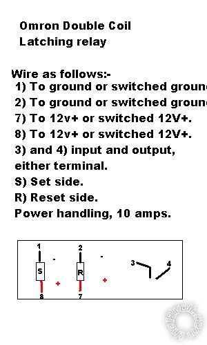
hi, a dual coil latching relay, i believe, will fit your application. an electronics distributor, such as Allied, Newark, or Mouser should have them. could also be done with electronic components. m
Posted By: akuhead
Date Posted: April 04, 2010 at 6:34 PM
Ween Thanks for the reply. I'll look into those distributors Jim
Posted By: KPierson
Date Posted: April 04, 2010 at 7:37 PM
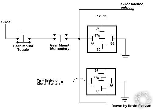
This would acomplish what you are asking. May I ask why you don't speed reference it and automate the entire process? It wouldn't take much more and you could make the unit operate more like stock. With this setup you'll have to reengage each time you hit the brake (or clutch depending on how you hook it up). ------------- Kevin Pierson
Posted By: vincent501
Date Posted: June 05, 2011 at 6:50 AM
KPierson
how would it work with a speed reference to automate the process?
This would create 2 issues,
A) how would the overdrive disengage or kickdown a gear when extra power is needed, while within the active/trigger speed range?
B) how would you prevent a kickdown gear shift from OD to the next downward gear, assuming at that point the speed of the vehicle would mean that the rev's are above the max limit of the engine.
thanks vincent501
Posted By: KPierson
Date Posted: June 05, 2011 at 8:12 AM
I've never worked with a Gear Vendors unit - the OP was the one who stated that generally there is a speed regulator involved. I have no idea what kind of functions said speed regulator provides.
-------------
Kevin Pierson
Posted By: howie ll
Date Posted: June 05, 2011 at 10:19 AM
This is what Ween has suggested, not sure if the serial number is
Omron G6CK-1114P-US12DC
or G6CK-2114P-US12DC.
Available from Mouser or Farnell. omron_g6ck-_2114p-us12dc.bmp------------- Amateurs assume, don't test and have problems; pros test first. I am not a free install service.
Read the installation manual, do a search here or online for your vehicle wiring before posting.
Posted By: michael henry
Date Posted: June 26, 2011 at 3:16 PM
Hi all,
I'm new to the forum, I have been searching for a simple wiring diagram for an overdrive (Gear Vendor) I acquired for my work truck. Nothing special just a 1982 Chevrolet C/20 (owned for 20 years) with a 383 small block and a turbo 400 built for pulling the weight of the truck and my work tools with little effort, it moves up to 65 MPH with ease to merge onto freeway traffic, cruising at 65-70 MPH and 3000-3500 RPM takes it toll on all the motor's accessories and eating fan belts as the truck was not designed for these speeds being built in 1982 when the speed limit was 55.
I would like a simple wiring diagram without purchasing the the manufacturer's fancy shifting stuff. Just real simple, I do not want the overdrive to engage while driving in town, just wanting to upshift/downshift into overdrive on the freeway with a foot switch. If any of you have a quick way to wire this or willing to offer more suggestions they would all be welcome.
The diagram in this thread is more than what I would want as I do not want the overdrive to disengaga while slowing on the freeway.
Thanks,
Mike ------------- Michael-Aznativephoenix
Posted By: KPierson
Date Posted: June 26, 2011 at 7:21 PM
I would think that you could find a latching foot switch - like the type that used to be used to turn bright lights on - and wire that up directly. You would just need to manually engage and disengage as needed.
-------------
Kevin Pierson
Posted By: michael henry
Date Posted: June 28, 2011 at 9:49 PM
Thanks Kevin,
I spoke with Gear Vendors, there is a signal generator (no polarity) that couples/splices in the speedometer cable to send a signal to the control unit (Gear Vendors control unit) so it does not engage below 20-25 MPH and set to engage at about 40-45 MPH, the overdrive solenoid (no polarity) that engages the overdrive is electric over hydraulic type, the unit has an internal pump to pressurize the the system and hold it in overdrive at high speeds and under the low speeds it cannot engage and damage the unit.
I was told by the factory that the signal generator produces 1-3 volts AC when driving, could this signal generator be used to keep the unit from engaging at low speeds if I fail to disengage the unit via the foot switch when coming to a stop? I'am going to purchase a new signal generator to check the type of signal it is sending..(Variable 1-3 volts?) and find a way to wire it.
I would post a PDF of the factory wiring diagram but the rules do not allow me. I could post a link to a site I found the diagram on but not sure if it is allowed.
Your time is appreciated, let me know if this make any sense.
Mike ------------- Michael-Aznativephoenix
Posted By: KPierson
Date Posted: June 29, 2011 at 7:02 AM
The speed sensor is most likely just a magnetic pick up. Without circuity you won't be able to connect that directly to your control system.
You could mount two magnets and a pickup to your output shaft and then get a frequency switch to accomplish what you are looking for (assuming you don't have an OEM VSS).
-------------
Kevin Pierson
|