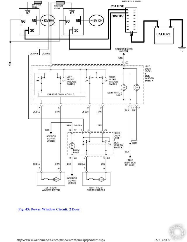
I was just wondering if the circuit I have drawn will be ok for daily use. I posted this same diagram on another website, and was told it would work but he didn't know how long it would be before the wires burnt and/or fuses kept popping. Let me know what you guys think. Originally the power was fused from a single 30A breaker, split into both green wires.
[IMG]https://i256.photobucket.com/albums/hh200/juavos/windows.png[/IMG]
I don't see a point either - what are you trying to acomplish?
There should never be a point that the wires burn. As long as you use the correct size wire and fuse it appropriately burning shouldn't be a concern.
-------------
Kevin Pierson
It reminds me of a recent circuit where the relays are on with ignition but AFTER a prior switch that does the on-off power connection.
You have a similar setup, and even have 20A circuit breakers in series with 20A fuses.
To off-load the switches, the relays should be between the switches and the motors - ie, just above the window motors in your diagram above (below all the switches).
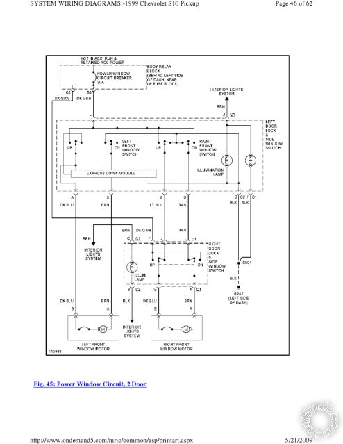
Sorry should have posted the original schematic from the trucks factory wiring so you can have a better look. Basically below shows that GM used a single relay/circuit breaker (30A) to split into two green wires that control the power for the window switches. I am not changing anything after the green wires, I am only changing how the green wires get power.
Because this truck did not have factory power, and I am in the process of wiring everything using mostly factory wiring/switches there are some things that I have to change because I don't want to run two relay/fuse boxes in the cab. Also the wiring that GM used is probably a slight bigger gauge than the one I am running. I am going to run 16AWG for mostly everything, except the power from the new fuse panel to the relay will be 14AWG. So I thought that I basically just finished with the original wiring, except split the power into half as much on each circuit. Because I don't want the windows to work without the ignition being on.
Still not sure if I see the point (though I'm not analysing in detail; but aren't the switches in series...?).
But you certainly do NOT need all the above - just insert the extra circuit breaker(s). (IE - remove one of the greens and run thru its own breaker.)
There is no need for relays, fuses etc.
And how did you arrive at the 20A protection figure? Why not 2 x 30A or 2 x 15A etc?
Or maybe WHY are you modifying? Breaker blows when both windows actuated?