constant to momentary with a microrelay
Printed From: the12volt.com
Forum Name: Relays
Forum Discription: Relay Diagrams, SPDT Relays, SPST Relays, DPDT Relays, Latching Relays, etc.
URL: https://www.the12volt.com/installbay/forum_posts.asp?tid=121707
Printed Date: April 01, 2026 at 11:38 AM
Topic: constant to momentary with a microrelay
Posted By: FLcruising
Subject: constant to momentary with a microrelay
Date Posted: May 06, 2010 at 8:35 AM
I tested this last night using the capacitor/resistor values as the diagram. When I power it, there's a noticeable sound that starts then fades away, but the relay doesn't engage? I held power to it for about 10 seconds to see if it would engage the relay, but nothing. Where did I mess up this simple circuit at? Testing the relay afterwards by itself it engages just fine. ------------- Aaron
Replies:
Posted By: anonymous1
Date Posted: May 06, 2010 at 9:05 AM
Please show exactly the diagram or schematic you followed to ensure we're all on the same page here. List the exact part #'s you are using, not generic descriptions. "I held power to it for about 10 seconds" = What pwr are you referring to? 9v battery or 12v car battery? Adapter? THX ------------- I know just enough to be dangerous. VERY dangerous.
Posted By: FLcruising
Date Posted: May 06, 2010 at 9:49 AM
Posted By: FLcruising
Date Posted: May 06, 2010 at 10:28 AM
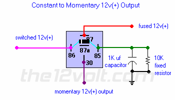
I have been looking at this diagram for 2 weeks now with the wrong idea in mind. I thought it energized the relay coil AFTER the capacitor charges, where actually it does BEFORE. I thought of it as a delay ON circuit, not an instant ON - delay OFF. Me = Idiot! Now that tha's cleared up, is there a relay/capacitor/resistor configuration that would (allowing me to use the parts I've already purchased) delay a relay turn ON by about 1/2 a second? ------------- Aaron
Posted By: 91stt
Date Posted: May 06, 2010 at 4:46 PM
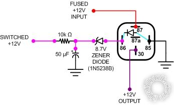
I threw the following together quickly (much appreciated if someone would be so kind as to check to make sure I got it correct) but it should be what you want.
Posted By: 91stt
Date Posted: May 06, 2010 at 4:51 PM
You may not be able to find a 50μF capacitor, so you may need to substitute a 47μF instead. It will still give you about a 500 ms delay.
Posted By: FLcruising
Date Posted: May 06, 2010 at 9:17 PM
Thank you 91stt, I actually have a 50µF capacitor, but it is bipolar. Could I just add a diode between it and ground with the stripe towards the cap to make it work? May I ask why the zener is not pointing towards the relay? ------------- Aaron
Posted By: dualsport
Date Posted: May 08, 2010 at 10:05 AM
91stt] wrote:
Unfortunately that won't work because the amount of current through the inline resistor won't be enough to drive the relay directly.
To do this you'd need a transistor driver.
This is a thread for momentary to timed pulse output stretching, but it's a simple matter to rearrange things for delayed on purposes.
post
Most people are highly resistant to using solid state devices, but they're really the way to go because it makes things smaller and cheaper; no huge capacitors are needed for long delays.
Posted By: FLcruising
Date Posted: May 08, 2010 at 12:46 PM
How would I rearrange things to get the delay ON? I'm not scared of solid state devices, I would just rather use parts from Radio Shack since it's close and I don't have to pay for shipping.
-------------
Aaron
Posted By: dualsport
Date Posted: May 08, 2010 at 3:32 PM
If you basically use the configuration above, but move the diode (a standard 1N4001 will do) and place it in parallel with the resistor (pointing to the left), you'll have a timed output you can feed to the transistor relay driver (refer to the drawing on the other post)
When your input goes high, it'll start charging up the capacitor through the resistor. Once the voltage reaches the turn on point of the transistor, about 3 or 4 volts, it'll turn on and switch the relay on.
when you turn off the signal, the diode will discharge the cap immediately and it should turn off right away.
Posted By: FLcruising
Date Posted: May 10, 2010 at 12:57 PM
But won't the cap only discharge immediately if the switched input goes to ground when turned off?
-------------
Aaron
Posted By: FLcruising
Date Posted: May 10, 2010 at 1:48 PM
Posted By: 91stt
Date Posted: May 13, 2010 at 5:35 PM
I knew something didn't look right when I uploaded the image.
The following incorporates the NPN transistor that you can get from RS.
It also includes the diode across the resistor so that the cap can discharge quicker.
The zener diode is in the correct orientation.
It looks odd but I inserted it there to basically force the capacitor to charge to nearly battery voltage before turning on the transistor.
You may have to substitute a 1N5237B, which is a 8.2V zener, instead if it is not turning on consistently.
You can probably get away without using it if you can't find one.
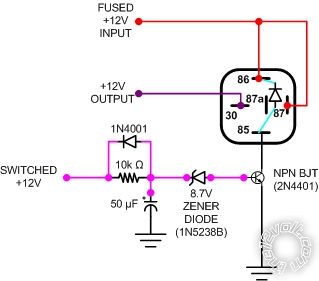
Make sure you have the quenching diode across the relay coil, otherwise the transistor may get fried when the relay is turned off.
|