Print Page | Close Window

water injection system eating relays

Printed From: the12volt.com
Forum Name: Relays
Forum Discription: Relay Diagrams, SPDT Relays, SPST Relays, DPDT Relays, Latching Relays, etc.
URL: https://www.the12volt.com/installbay/forum_posts.asp?tid=122475
Printed Date: May 06, 2024 at 12:36 AM


Topic: water injection system eating relays

Posted By: emd_driver
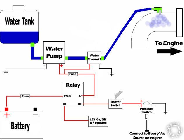
Subject: water injection system eating relays
Date Posted: June 29, 2010 at 3:31 PM

Hello,

I'm new here and this is my first post.

I installed a water injection system on my truck and it's eating relays. Here's a diagram of the system:

posted_image

The problem I am having, is due to the nature of the Powerstroke engine. The turbo output is pulsed and causes the pressure switch to "Flicker" the relay on and off quickly.

I'd like to know if adding a short-term capacitor across the coil of the relay would help smooth it out. If not, I'm VERY oppen to suggestions!

Gary


Replies:

Posted By: i am an idiot
Date Posted: June 29, 2010 at 8:24 PM
Paralleling a capacitor across the coils should help you out.  I do not remember if a 4700 mic cap will hold it for 1/4 or 1/2 second.


Posted By: emd_driver
Date Posted: June 29, 2010 at 9:47 PM
i am an idiot wrote:

Paralleling a capacitor across the coils should help you out.  I do not remember if a 4700 mic cap will hold it for 1/4 or 1/2 second.


Can you help me out with identification? I need to know exactly what to look for, as I'm terminology impaired..


Posted By: i am an idiot
Date Posted: June 29, 2010 at 9:56 PM


Posted By: emd_driver
Date Posted: June 29, 2010 at 10:04 PM
i am an idiot wrote:

https://www.radioshack.com/product/index.jsp?productid=2102508&filterValue=%244.00+-+%245.99&filterName=Price


Thank you!

Judging from the diagram above, does it matter which way it is wired in?


Posted By: i am an idiot
Date Posted: June 29, 2010 at 10:31 PM

The cap is polarized, notice the arrow on the side of it.  You can see it in the picture, the arrow denotes the negative connection of the cap.  Positive to 86, and negative to 85.


Posted By: emd_driver
Date Posted: June 29, 2010 at 10:43 PM
i am an idiot wrote:

The cap is polarized, notice the arrow on the side of it.  You can see it in the picture, the arrow denotes the negative connection of the cap.  Positive to 86, and negative to 85.


Thanks a ton!

Just so I don't screw it up.... The arrow points to 85 and the other end points to 86..

Thanks again!

Gary


Posted By: i am an idiot
Date Posted: June 29, 2010 at 11:33 PM
Correct


Posted By: emd_driver
Date Posted: June 30, 2010 at 5:38 PM
I picked up a cap and wired it in this evening. I had to replace another dead relay, so I added the cap to it, before hooking it up.

Went for an 80 mile test drive and the results are VERY promising!

There was a tiny bit of flicker, every once in a while. It was nothing like before and the system works great now!

I also noticed that the circuit stays energized a bit longer than before, just like you said it would. That does not affect the operation at all.

Thanks again!!

Gary


Posted By: i am an idiot
Date Posted: June 30, 2010 at 7:58 PM
Glad we could help.


Print Page | Close Window