relay bleed through cadi trunk pop dmm
Printed From: the12volt.com
Forum Name: Relays
Forum Discription: Relay Diagrams, SPDT Relays, SPST Relays, DPDT Relays, Latching Relays, etc.
URL: https://www.the12volt.com/installbay/forum_posts.asp?tid=122739
Printed Date: May 10, 2026 at 4:33 AM
Topic: relay bleed through cadi trunk pop dmm
Posted By: masterodisaster
Subject: relay bleed through cadi trunk pop dmm
Date Posted: July 18, 2010 at 11:23 PM
I am just curious when testing suspected circuits using a multimeter and you have a wire resting at a positive voltage (+12.6V) how can you determine if it is a negative trigger without potentially causing damage to the vehicle computer.
It is only an issue due to the multimeter my installer was using wasn't displaying the quick pulse of voltage properly. Are there certain specifications I should look for on a DMM that would be best for the automotive installer? I personally have $200 Snap On that works great, but my installer has a $100 Fluke meter and it is "slow to react to voltage changes"... I want him to have one that will have a higher "sample rate" if you know what I mean. In any case this Cadillac Deville we did today had a trunk pop listed as a (-) trigger, but it ended up being a (+) trigger and for some reason and I had a tough time determining it's trigger type with his meter (the wire stated it was located under the back seat by the Fuse panel and battery, and I was scared to feed (+12V)---> into this wire for fear of blowing up the ECU). I'm just curious how most of you guys handle this type of situation - I usually use my best judgement and feed a HIGHLY suspected circuit the polarity stated in the "Directechs info" (with a 1 amp fuse inline just in case). I know this is bad, and want to resolve my reluctance to feed a suspected, but not 100% sure circuits with voltage or ground to test their "activation" (could be light flash, door locks, trunk pop etc.)...
Thanks for all the input!
Keep up the good work!
 -------------
Replies:
Posted By: oldspark
Date Posted: July 19, 2010 at 12:56 AM
You could try an analog meter, or a LED.
It could be a good use for a test lamp, but experienced users should be able to advise & explain. (howie ll comes to mind.)
Or a logic analyser (with a 5V liniter/divider if required).
Or maybe a home brew "sample & hold" circuit (diode, capacitor).
Or some -ve triggered circuit...
The only way a typical digital meter will sense it is if it samples at the right time. Extending the sample time won't help. You need a DMM that has a peak-sample&hold function.
Analogs (ie, meter movements) may move fast enough to indicate a pulse.
And there is always the good old CRO....
Maybe others know of some suitable cheap instruments....
Posted By: KPierson
Date Posted: July 19, 2010 at 1:38 AM
The Fluke, if setup correctly, should read virtually any signal in a car. You MUST disable autoranging for pulses. What happens is the range exceeds the first autorange step and causes the meter to freeze just long enough that the pulse is missed. If you disable autoranging and only look at xx. or xx.x vdc. This should allow you to see the pulse.
Also, if you must "guess" at a signal I prefer to put a ~220 ohm resistor in line with a 1A fuse. This will theoretically limit current to around 50mA. ------------- Kevin Pierson
Posted By: i am an idiot
Date Posted: July 19, 2010 at 10:01 PM
Ditto what K said. You can not buy a better meter. The autoranging feature of the meter is why it is having trouble.
Posted By: i am an idiot
Date Posted: July 19, 2010 at 10:24 PM
Some Cadillacs have 12 volts on the arm that the trunk latches to. I see a lot of guys touching their meter lead to that piece of the car to check for voltage at an amp. When the trunk lid touches the arm it is grounded through the lid and the auto close motor pulls it down. Just an FYI, I know it is not related to your problem.
Posted By: howie ll
Date Posted: July 21, 2010 at 2:13 PM
Howie agrees with KP and Mr. I ref fluke meters but would still use a "fast and dirty test light" because the bulb protects.
Yes I recently triggered a DTC engine light on an MX8 probing the inst. panel but not being a VW it cleared after 10 secs.
Posted By: tommy...
Date Posted: July 24, 2010 at 3:02 PM
howie ll wrote:
Howie agrees with KP and Mr. I ref fluke meters but would still use a "fast and dirty test light" because the bulb protects.
Yes I recently triggered a DTC engine light on an MX8 probing the inst. panel but not being a VW it cleared after 10 secs.
... ------------- M.E.C.P & First-Class
Go slow and drink lots of water...Procrastinators' Unite...Tomorrow!
Posted By: howie ll
Date Posted: July 24, 2010 at 4:58 PM
Oh all right it was a dig at bloody VAG "catch the aftermarket out" software.
I'm debating how to raise the £4000 ($6000) for a decent diagnostic unit.
-------------
Amateurs assume, don't test and have problems; pros test first. I am not a free install service.
Read the installation manual, do a search here or online for your vehicle wiring before posting.
Posted By: dualsport
Date Posted: August 13, 2010 at 1:01 AM
masterodisaster wrote:
I am just curious when testing suspected circuits using a multimeter and you have a wire resting at a positive voltage (+12.6V) how can you determine if it is a negative trigger without potentially causing damage to the vehicle computer.
It is only an issue due to the multimeter my installer was using wasn't displaying the quick pulse of voltage properly. Are there certain specifications I should look for on a DMM that would be best for the automotive installer? I personally have $200 Snap On that works great, but my installer has a $100 Fluke meter and it is "slow to react to voltage changes"... I want him to have one that will have a higher "sample rate" if you know what I mean. In any case this Cadillac Deville we did today had a trunk pop listed as a (-) trigger, but it ended up being a (+) trigger and for some reason and I had a tough time determining it's trigger type with his meter
If the wire rests at 12.6V it probably isn't a + trigger- it generally needs to sit at the opposite state of whatever triggers it.
A DMM should be used prior to test lights or other devices that draw any appreciable current, when testing unknown signals.
As far as detecting fast pulses, the meter would need to have some peak detection or logic mode to pick it up reliably. The sampling rates of DMMs aren't fast enough to pick up very short pulses in normal measurement mode, even if set to fixed range.
If the meter doesn't have any suitable pulse detection modes, you could look for one that has the feature, and they're available on a lot of meters much cheaper even than the Fluke. Or you could put together a CMOS logic probe that will easily detect pulses, without loading the signal, which is necessary in case the signal is sensitive to injected current. Analog meters and test lights have much lower input impedances so they require more care with unknown circuits.
Posted By: howie ll
Date Posted: August 13, 2010 at 1:16 AM
Frankly if I was testing that wire and knew it's function, I'd use my trusty snap-On test light, lets face it you will know it's at rest polarity, pos or neg, then use the trunk release, that will tell you whether you have a trigger wire or a motor wirer and if it's polarity if a trigger or relay interrupt (5 wire) if it's a motor wire, simpler and much less time than it took me to write this.
-------------
Amateurs assume, don't test and have problems; pros test first. I am not a free install service.
Read the installation manual, do a search here or online for your vehicle wiring before posting.
Posted By: masterodisaster
Date Posted: August 13, 2010 at 1:54 AM
I realize that (-) triggered circuits usually show a (+) and same the same thing with (+) triggered circuits resting at or close to ground - hence the "relay bleed" part, but just having the guts to put the opposite polarity to that wire scares me sometimes (there are times when I'll test a set of lock wires that don't really show any significant change on my meter using the lock switch, but when I probe the questionable circuit with voltage or ground it activates the locks).
I like the idea about putting a resistor inline on the 1 amp fuse as well.
Our shop is one that doesn't allow test lights of any kind, not even "computer safe test probes". I will look for something like dualsport said - "pulse detection mode".
Any recommendations for a good ~$200 meter?
Thanks guyz!
-------------
Posted By: oldspark
Date Posted: August 13, 2010 at 3:05 AM
masterodisaster wrote:
.... but just having the guts to put the opposite polarity to that wire scares me sometimes...
Maybe I'm missing something (though I know what you mean....) but polarity is irrelevant from a testing POV - keeping in mind that a test lamp is a resistor that limits current (ie ~80 Ohm for a 2W bulb).
Or use back to back LEDs for lower currents....
It doesn't matter if you bridge "down to" GND or "up to" +V.
This is not to be confused with switching - ie, whilst it is ok to parallel-connect grounds (ground switching), it is not ok to parallel different control voltages - especially if they are different. But they are shorted together whereas a test light, or voltmeter, has impedance. (But not an ammeter.)
I never liked test lights - instead preferring my DMMs etc.
But there are times when a test light can do what a DMM can't.
And test lights can function as handy non-destructive triggers - though I get the impression that's not always intentional lol.
Not long after starting on this forum, I was determined to get/make a test light. I reckon I still will. One day. Then I won't have to be so careful testing hot leads (eg - is it +12V through the dome light, or raw +12V??).
Your shop sounds a bit primitive. If they do not allow lights, I presume they have logic probes, state analysers, or CROs. Else sophisticated sample & holds etc.
But a $2 LED or light is probably cheaper etc.
(Is there a valid reason - or is it another case of misunderstood technicalities, or "a little knowledge...."?)
Posted By: masterodisaster
Date Posted: August 13, 2010 at 4:29 AM
Well from what I'm told "test lights" pull too much current through the light and can "damage vehicle computers", so this is why we aren't allowed to use them. I've been doing car audio a long time and have never damaged a computer yet (knock on wood)... I used to use a type of test light that used 2 leds (one red (+) and one green (-) and it worked great, but was told it could still damage a vehicle computer, so I only use it on "older" cars. Anyway we have to pay for our own tools and I can't afford high priced oscilloscopes and analyzers on installer salary. I don't know what you mean by "misunderstood technicalities" or "little knowledge" - maybe "I ain't none too smart", but that is why I'm asking for opinions. For me at least - polarity matters when you have to trigger a circuit and you don't know which polarity it requires to do so. Giddyup!
-------------
Posted By: oldspark
Date Posted: August 13, 2010 at 5:26 AM
Master - I wasn't thinking of you, nor criticising.
You are smart - you are here! (And I ain't too smart on test lights - it's a relatively recent awakening for me. But the experienced on this site have a few good stories and uses...)
The over-current draw is a valid reason for not using test lights and that's where logic probes come in.
But most CPU outputs should be robust enough.
Some Delco literature from the late 1980s said something like test lamps under 2.5W or 3.4W or similar were ok for any testing. (Except f.ex things like the oxygen sensor/s that you don't even test with a DMM - definitely not on resistance scale anyhow!)
But that was then and circuits have changed.
Though I'd reckon low power LEDs should be okay - most things will handle a few mA. But that defeats some of the advantages of a bulb type tester (I think?).
My "misunderstood technicalities" & "little knowledge" was directed at all too common misunderstandings that often lead to the wrong or opposite solution. (Why do I think if The President's "Internet Shutdown" button in case of a terrorist attack? But that was a April Fool's joke.)
But incorrectly used DMMs can blow ECUs, as can static discharges and a host of other things. And in a market that tends to de-ruggedise equipment in favor of revenue, playing safe is good.
But I'll leave the lite discussion to the experts.
Good luck! (I'll be reading their replies too!)
And if I remember where I recently saw the cheap mini-LCD CRO for some crazy $50 or $150 - and it seems ok - I'll let you know.... (eBay??)
Posted By: howie ll
Date Posted: August 13, 2010 at 1:08 PM
The rule about no test lights is ridiculous; its a "My way or the Highway" attitude. If someone comes up with a great idea, do the powers that be listen?
I have a DMM but I will only use it in testing when I think I'm hitting on data wiring.
Even with BCM inputs I can assure you that using an incandescent bulb tester is fine because you're looking at trigger wires and they will either change polarity or go from open to closed circuit.
That tester you mentioned, somewhere under my 4 Weller Pyropens I have one, wonderful for finding tach quickly. Think it was a Mac 120 or Snap-On equivalent.
I guarantee I will find door trigger contacts or door lock triggers/motor wires faster with a test bulb than with a DMM.
Anyway if I screw up I've got $6000 of diagnostic gear to clear it.
-------------
Amateurs assume, don't test and have problems; pros test first. I am not a free install service.
Read the installation manual, do a search here or online for your vehicle wiring before posting.
Posted By: howie ll
Date Posted: August 13, 2010 at 1:10 PM
As an addenda, I'd rather state don't pull airbag connectors or control units with the ignition on!
-------------
Amateurs assume, don't test and have problems; pros test first. I am not a free install service.
Read the installation manual, do a search here or online for your vehicle wiring before posting.
Posted By: masterodisaster
Date Posted: August 13, 2010 at 3:02 PM
Yeah howie - I agree that it is closed minded to say "NO TESTLIGHTS PERIOD", but this is a very large chain of stores that has some serious amateur installers working for them. They don't really care about how fast you are, just that you aren't causing vehicle damage that costs them money. I'm still unsure how test lights do damage, but I'm taking their word that it does happen - so the dude abides. I'm looking at the new Fluke 287 DMM that has "event recording" on the display - looks pretty sweet. Now I just need to scrape up $400 or so.
oldspark - no sweat - I bought one of those cheap LCD mini CRO's" - it's pretty cool, but I'd still like a real one. The instructions are all in Chinese (did find a few English instructions on the web), and it just doesn't feel like the real thing.
search "arm dso portable mini" on Ebay - I picked mine up for $85 shipped.
CRO=Cathode Ray Oscilloscope/Oscillograph for all you noobs.
Thanks guys - I'm really diggin this forum.
-------------
Posted By: dualsport
Date Posted: August 15, 2010 at 10:54 AM
Fluke 287 seems a bit of overkill for simple pulse detection, but if some future use can use its capabilities, it's good to have-
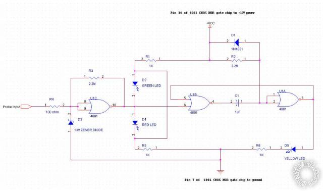
If you're so inclined, you can put something like this for just pennies and your time.
It won't draw down your test signal as it's high impedance, and detects the presence of any brief negative going pulse triggers by stretching out the yellow LED on time.
It does need a connection to power, which can be vehicle supplied or you could use a battery. In that case you just connect the ground to the car's ground, and just supply the probe signal input.
Note if you're looking for a single shot positive going pulse the circuit would have to be modified first.
Posted By: masterodisaster
Date Posted: August 15, 2010 at 8:33 PM
dualsport - you are THE man. Fluke 287 is definitely overkill. Might I ask where you got this diagram? What do the red, green and yellow LEDs indicate?
I'll have to give this diagram to my electrical engineer buddy.
Thanks!
-------------
Posted By: dualsport
Date Posted: August 15, 2010 at 9:06 PM
The logic probe just uses some CMOS gates which are very high impedance inputs to drive the indicator LEDs. The 2.2M resistor will put a slight current on the input, but it's minimal enough not to worry about. The purpose of that resistor is to feed back and toggle when nothing's connected to the input, which is handy as an indication that your signal is an open circuit vs. an actual high or low.
You could just remove the 2.2M resistor if you don't need to try detecting an open circuit. Add a 10M pulldown resistor on the input in that case. Only thing If you do that is the red LED will be on by default even if you're probing an open circuit, so you won't be able to tell if it's a real ground you're connected to or not.
The green LED lights up when the input is high, and the red lights up when it's low. The Vcc voltage you use for the circuit determines the transition threshold; it's half the voltage. You might try using a 9V battery for power if you want to avoid having to connect up 12V separately to it, should still be okay for 12V signals.
The yellow LED indicates the presence of a pulse on the input; if there's a signal that's constantly toggling up and down, it'll light up continuously.
If a single negative going transition occurs, it'll light up for a few seconds before going off again. It could be modified by using the last gate in the chip to invert the incoming signal if you need to detect a single positive going transition.
Posted By: dualsport
Date Posted: August 15, 2010 at 9:14 PM
By the way, how is that ebay "arm dso portable mini" ?
Seem like it might be an interesting little thing to play around with- have you found it to be actually useful?
Rather low sampling rate as DSO's go, but it looks like it would be handy to have around, being so portable. Battery life decent?
Posted By: masterodisaster
Date Posted: August 15, 2010 at 9:55 PM
So far battery is excellent, and it works great for reading RCA output clipping, but that's about all I've done with it. So many fancy settings I'm not familiar with, but I'm sure as my buddy is going through EE Schooling he'll want to fill me in on all how all those type of measurements function. Is there a more detailed picture of that diagram? A few characters are a bit fuzzy.
Keep on rockin!
-------------
Posted By: dualsport
Date Posted: August 15, 2010 at 10:05 PM
Sounds good, I might get one to play with-
Yeah, the jpg was low resolution to meet the limitations of the upload sizes here; I'll get a better one to you when I get the chance. You don't really need the details like the pin numbers if you look up the part's datasheet though-
Posted By: dualsport
Date Posted: August 15, 2010 at 10:13 PM
https://www.mouser.com has the datasheet, the other stuff should be common items you could probably pick up at the local supermarket-
Posted By: masterodisaster
Date Posted: August 16, 2010 at 3:34 AM
"The 2.2M resistor will put a slight current on the input, but it's minimal enough not to worry about."
-dualsport
Based on this thought, and since these diagrams have blown my mind, can you attempt to explain what types of currents or voltages would potentially cause damage to even the most fragile circuits in a vehicle?
---------
One of my former superiors said "computer safe test lights can still potentially cause damage to modern vehicle electronics". Is there a way to prove him wrong about my Snap-On (GREEN/ red) LED light? Could I use my DMM to "test the test light" and see if it passes the test? Hehe... I used it for years without a problem, then the "no test light rule" came into effect.
Know what I mean? I miss my dang light! :(
I will try again shortly to comprehend that diagram and what it would allow me to do, unless I find out my computer safe light actually is computer safe...
Yall have been great - Thanks again!
-------------
Posted By: dualsport
Date Posted: August 16, 2010 at 6:06 PM
I don't know how the Snap-On test light is designed, so I couldn't really say what it might do. If it's an expensive item, as I would guess it is, I'd assume it's more sophisticated than a simple LED connection that runs off the input signal.
If you take something like a 1M resistor or larger, connect it between your test light input and 12V, and measure the voltage with your DMM, you should see 12V. Then if you connect the resistor between the test light and ground, you should see 0V. That indicates your test light isn't putting any appreciable current out to the signal under test. If, however, the test light overrides the pullup and goes to some voltage regardless of how you connect your pullup, it's putting a load onto the signal, and it might be an issue, depending on how much it is. You could try with progressively lower resistor values until you see the voltage change, if you were interested in just how much of a load it is.
6 microamps is unlikely to cause damage, if automotive electronics were sensitive enough to be damaged by that, we'd have to be careful about sneezing around them- 
Posted By: KPierson
Date Posted: August 16, 2010 at 6:17 PM
I've always heard the issue with test lights was only with the incandescent style (the old ones). They pull a decent amount of current and they can set air bags off. I've never heard of anyone damaging a computer with a test light but I have heard of multiple people setting off air bags with them.
I've personally never use a test light at all - I rather use a cheap Craftsman meter with "bed of nails" alligator clips. When I'm looking for a quick pulse I'll pull out my fluke, but for "everyday" use the Fluke is overkill and not worth losing / damaging. I'm guessing (or hoping anyway) I am not the only one that has actually ran over a multimeter in a bay.... :) ------------- Kevin Pierson
Posted By: dualsport
Date Posted: August 16, 2010 at 10:27 PM
KPierson wrote:
I'm guessing (or hoping anyway) I am not the only one that has actually ran over a multimeter in a bay.... :)
You got me there- never did that, but did you ever drop a DMM off the back of a motorcycle when the luggage lid flew open without your knowing, and continuing to ride merrily along for miles and scattering all sorts of goodies on the highway as they flew out with every bump? 
Posted By: i am an idiot
Date Posted: August 16, 2010 at 10:45 PM
Not quite running over a meter, but I did witness somebody back a car out of the bay with a fluorescent drop light ran through the door. He said he knew something happened when the car suddenly got darker inside.
Posted By: howie ll
Date Posted: August 17, 2010 at 2:14 AM
I know I'm going to be skinned alive but yes, it's an incandescent bulb test light.
Having said that, I've been in this business since the early 70s and you learn common sense and evolve or else.
Discretionary use is how I would describe it.
Forget computers, air bag wiring and CAN signalling lines are the problems.
Never seen permanent damage from working on processors, come to think of it I always thought the stories of air bags going off whilst working on cars was an urban legend.
And yes even with fluorescent Snap-On tool handles, I still leave the damn things under seats. What next, RFID chips in the handles?
-------------
Amateurs assume, don't test and have problems; pros test first. I am not a free install service.
Read the installation manual, do a search here or online for your vehicle wiring before posting.
Posted By: i am an idiot
Date Posted: August 17, 2010 at 7:02 AM
Howie, I have never heard of anybody setting an airbag off with a test light..(anybody I know personally) But I can tell you that the airbag deployment circuit reads around 4 ohms, so when you use a makita battery to figure out which speaker wire you have, you do hear a sound from all sides and corners of a Range Rover.
Posted By: howie ll
Date Posted: August 17, 2010 at 7:13 AM
Huh? Another one after my own heart, hate those muppets with their AA batteries, personally I use the radio harness constant and ground, just need spare fuses, mind you a Snap-On test light is safer, N.B. All this pussyfooting, any one remember 90s BMW 5/7 series, with all the inherent electrical noise they had?
It's alright taking precautions and preparation but how anal do you want to get?
-------------
Amateurs assume, don't test and have problems; pros test first. I am not a free install service.
Read the installation manual, do a search here or online for your vehicle wiring before posting.
Posted By: dualsport
Date Posted: August 17, 2010 at 7:18 AM
no more 'n 3 or 4 inches, I reckon-
Posted By: howie ll
Date Posted: August 17, 2010 at 7:29 AM
Ha Ha I'm now going to buy Snap-On shares so I will "insert" (Oldspark isn't the only one with terrible puns) Snap-On incandescent bulb testers into every post. Just did it with a cellular query.
-------------
Amateurs assume, don't test and have problems; pros test first. I am not a free install service.
Read the installation manual, do a search here or online for your vehicle wiring before posting.
Posted By: oldspark
Date Posted: August 17, 2010 at 7:44 AM
Gentlemen PLEASE - for PETE's sake!!!!
7.5 to 10 centi-meters!!!
What are we? American?
Besides, it sounds bigger.
PS - Ouch.
PPS - I did mention LEDs etc. Hi-impedance. (Down here we use domestic bulbs, though curly CFLs are proving popular.)
|