2 potentiometers, one circuit
Printed From: the12volt.com
Forum Name: Relays
Forum Discription: Relay Diagrams, SPDT Relays, SPST Relays, DPDT Relays, Latching Relays, etc.
URL: https://www.the12volt.com/installbay/forum_posts.asp?tid=123168
Printed Date: May 09, 2026 at 3:08 PM
Topic: 2 potentiometers, one circuit
Posted By: micrors4racer
Subject: 2 potentiometers, one circuit
Date Posted: August 19, 2010 at 6:38 AM
I have a rev-limiting board in my car that helps limit it to 6.5k rpm using a 3 wire potentiometer. I want to add another potentiometer set lower to around 3k rpm so that when my ebrake is up (using that ground switch built in that normally turns on that little BRAKE light on your dash) it by passes the 6.5k potentiometer and uses the one set for 3k rpm and when the ebrake is released it goes back to the original potentiometer set at 6.5k rpm.
I was told a DPDT relay would work with this but i'm unsure of how to wire it up.
Replies:
Posted By: i am an idiot
Date Posted: August 19, 2010 at 7:35 AM
I need a diagram of how the pots are connected to the vehicle to be able to help you.
Posted By: KPierson
Date Posted: August 19, 2010 at 8:20 AM
A SPDT relay should work as well, assuming the module just needs a voltage input.
I would assume one side of the pot is connected to voltage, one side is connected to ground, and the middle leg goes to the rev limiter. If that is the case tie the middle leg of the existing pot to pin 87A of a standard automotive relay. Connect your second pot in the same fashion and connect its middle leg to pin 87. Connect pin 30 to the input on your box.
Connect pin 85 to ground and connect pin 86 to your brake light circuit. ------------- Kevin Pierson
Posted By: oldspark
Date Posted: August 19, 2010 at 10:01 AM
You might even be able to use the switch to connect (else short) the 2nd pot if they are grounded... (and 3kRPM is less resistance than higher RPM).
Posted By: micrors4racer
Date Posted: August 19, 2010 at 5:01 PM
Thanks guys, Kpierson I will try that out once I get a hold of a SPDT relay. As far as the diagram, there is none because this rev limiter was made using a Autometer tachometer and the shiftlight output activating a relay that grounds the ignitor coil. But I have a volt meter so I can tell you guys some stuff if you tell me how to test it.
Here is a diagram of how the tach is connected. However its no longer the full tach, just the circuit inside a project box so that it looks better.

Here are the wires that connect to the potentiometer. Turning it clockwise decreases the revs and counter clockwise increases it. It is a 10K pot. 
Posted By: oldspark
Date Posted: August 19, 2010 at 7:02 PM
If that pot is grounded at one end, the "new" pot or resistor may be able to be connected in parallel with the grounding switch grounding it. But if that switch is connected to something else, then a relay (SPST) etc may be required.
Posted By: micrors4racer
Date Posted: August 19, 2010 at 7:51 PM
Well i tested the voltage on the contact points. Orange wire is 7v yellow is 2.9v and green is 1.8v so i guess none of the points are ground?
Posted By: i am an idiot
Date Posted: August 19, 2010 at 8:19 PM
The output range of your device is from 1,8 volts to 7 volts. The yellow wire, is the adjustable wire. Depending on the position of the shaft the output will be somewhere between those 2 voltages.
It may affect the device if you were to parallel a second pot and use the relay to determine which center leg the system would see. I really think you should use a 3PDT relay. Radio Shack should sell one. Get one and post a picture of the diagram of the relay and I can lead you in the right direction.
Posted By: micrors4racer
Date Posted: August 19, 2010 at 8:45 PM
When searching their website nothing comes up with 3PDT or TPDT. No way to do it using a SPDT or a SPST relay?
Posted By: oldspark
Date Posted: August 20, 2010 at 12:25 AM
Even if not grounded, it only needs an SPST relay.
If there is a resistor from green to gnd (and nothing else) that could be moved to the orange side, then only the switch is needed.
Maybe only the switch is required anyhow since - when the switch is open - the parallel resistor will be disconnected.
You don't have the circuit diagram, or a pic of the PCB?
Posted By: micrors4racer
Date Posted: August 20, 2010 at 6:33 PM
I took some high res pics of the board for you. They are quite large for detail so I'll link them instead of embed.
Over all view
https://img.photobucket.com/albums/v446/micrors4racer/DSC00057.jpg
Top part
https://img.photobucket.com/albums/v446/micrors4racer/DSC00062.jpg
Bottom
https://img.photobucket.com/albums/v446/micrors4racer/DSC00061.jpg
Left side with the pot wires
https://img.photobucket.com/albums/v446/micrors4racer/DSC00060.jpg
Detail of left side
https://img.photobucket.com/albums/v446/micrors4racer/DSC00059.jpg
There seems to be some potting compound applied to the board to prevent components from vibrating loose inside the tachomter it was install in.
Posted By: i am an idiot
Date Posted: August 20, 2010 at 6:50 PM
You may be able to do it with a SPDT relay as suggested. However, paralleling a second potentiometer across the original one may cause unwanted irregularities in the control unit. I was suggesting the 3 pole device so there will be only one pot connected to the unit at any given time.
Posted By: micrors4racer
Date Posted: August 20, 2010 at 7:40 PM
How would it be wired up with a standard relay just incase I can't find a tpdt? I'm going to look for one now but I need a back up incase I can't find one. Have a track day on Sunday that I want to test this out in
Posted By: i am an idiot
Date Posted: August 20, 2010 at 8:09 PM
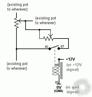
You could use 3 separate SPDT relays to make a Triple Pole Double Throw device. If you want to try it with a single relay, connect the left most terminal of the second pot to the leftmost terminal of the original pot. Connect the rightmost connections as well. Cut the center wire between the pot and device. Connect the device to terminal 30 of the relay. Connect the original pots center tap to terminal 87A or the relay. Connect the center terminal of the second pot to terminal 87 of the relay. Connect power to terminal 86 of the relay. Connect terminal 85 to the parking brake wire.
With the parking brake off, the pot that is connected to terminal 87A will be the one in use. When the parking brake is engaged, the control that is connected to terminal 87 is going to be the active one.
To use the 3 relays to make the triple pole device, connect it as follows. One relay per wire color. Terminal 30 to device. Terminal 87A to the pot that is active when the brake is off. Terminal 87 to the pot that is to be active when the brake is engaged. Power to terminal 86 of all 3 relays. Parking brake wire to 85 of all 3 relays.
Posted By: oldspark
Date Posted: August 20, 2010 at 8:22 PM
i am an idiot wrote:
...paralleling a second potentiometer across the original one may cause unwanted irregularities in the control unit...
Sorry Idiot, but I strongly disagree (given common liklihoods).
Any relay should have similar irregularities through noise etc.
The impacts of three break before make contacts for a control pot?
But a single SPST is 1 or 2 wires as opposed 3 or 6.
And there is no break before make issue.
And what am I missing? I thought a second pot/resistance was to be switched in somehow for the second RPM cut setting. Hence either changing over to another pot (your method?) else changing the pot setting (my method).
Not that I've looked at the pics yet.... Nor drawn a simple pic....
This is the quickie I'm having before picking up my girlfriend (after I vote at our federal elections). I love our freedom of speach & democracy - voting is compulsory (or else!).
Posted By: oldspark
Date Posted: August 20, 2010 at 8:45 PM
Ok - downloaded the pics (NICE!).
Can you post one of the trackside?
Just one like DSC00057.jpg should do (but from the opposite side!).
The CS289 is just a tacho chip.
The LM358 is a (quad) Op-Amp that will be doing the threshold comparisons....
Gotta love these primitive discrete circuits (as in no PICs etc!)
Posted By: micrors4racer
Date Posted: August 20, 2010 at 11:23 PM
Posted By: i am an idiot
Date Posted: August 21, 2010 at 7:22 AM
What is the value of the original potentiometer? Paralleling a second one of the same value will put twice the load on the device. If you can find 2 pots of around twiice the resistance as the original, there will be absolutely no channce of any damage. Both pots paralleled will yield the same stress on internal components. The pot is used as a potentiometer and not a variable resistor, so operation will be the same regardless of value. I have not looked at the pictures or pulled any datasheets. But this could be the same as running a 4 ohm capable amp at 2 ohms.
Posted By: micrors4racer
Date Posted: August 21, 2010 at 4:30 PM
The pot is a B10K
Posted By: oldspark
Date Posted: August 21, 2010 at 8:04 PM
i am an idiot wrote:
Paralleling a second one {.....} will ... load .. the device
Stop and think...
It depend where it is connected.
If between the yellow & green (low voltage sweep) it has no effect (since this is a 3-wire pot, not 2).
And that was my thought. However, looking at the tracks, it seem the pot adjusts the tacho chip and not the op-amps - hence it seems like a scale adjustment (but that would effect the meter out of used).
As a rule, it doesn't matter what the 2nd parallel pot does - it merely provides the same resistance that the original pot can be adjusted to.
Posted By: i am an idiot
Date Posted: August 21, 2010 at 8:33 PM
So the same amount of voltage across a 10K load will draw the same current as it does across a 5K load? If both pots are connected, minus the wiper, it will be a 5K load vs. the original 10K. Chances are he will not hurt anything with this device, just trying to give all the information he might need to make an informed decision.
Posted By: oldspark
Date Posted: August 22, 2010 at 12:12 AM
Too many assumptions....
It's (probably) NOT across the 10K pot.
And if it were, chances are it would be more than a 10k pot (eg, 20k-50k).
Like I said, think about it.
Rarely in circuit like this would the pot be effecting an output (in a stress sense).
But also as I said, the pot is connected to the tacho chip (2 pins; I can't tell where the 3rd pot wire goes; yet) so it doesn't seem to be effecting the RPM cutout level...
Posted By: oldspark
Date Posted: August 22, 2010 at 3:45 AM
Here's what I was thinking....
Not that the direction of the original pot is arbitrary - the relay and new pot can be from the wiper to either end depending in the circuit....
Posted By: i am an idiot
Date Posted: August 22, 2010 at 5:17 AM
That is even worse. Place the wiper of the original pot at top of the stroke, now place the wiper of the added pot at the right end of the stroke. Now engage the parking brake. What kind of load is shown to the controller?
Original poster: Hold up a minute, do not attempt the last diagram shown until we get this sorted out.
Posted By: micrors4racer
Date Posted: August 22, 2010 at 5:43 AM
Alright I'll let you electrical masters decide because quite frankly I don't understand the issues with either methods. For tommorow I guess I will just use it as a launch control with no lower high rpm limit. Thanks for the help looking forward to a solution
Posted By: oldspark
Date Posted: August 22, 2010 at 6:14 AM
Nah - go with Idiot's suggestion.
Maybe I'm misinterpreting the whole thing (I thought you wanted a second rev limit given a certain trigger) including the "break before make" problems....
And I haven't deciphered the circuit past the 1k trimpot being between pins 9 & 11 of the CS289 (Vreg & SQout?) and ??? ....
(Not to be confused with the added pot as I confusingly replied earlier...)
Posted By: i am an idiot
Date Posted: August 22, 2010 at 9:27 AM
If you can find 20K pots, I would really reccomend doing it that way. If you can not, you will more than likely be OK with the 2 10K pots.
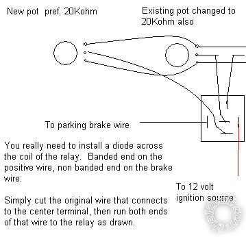
Notice terminal 30 of the relay is at the top of the picture. I did not draw the diode, but I think you need to use one. Instructions for diode are in the picture.
Posted By: micrors4racer
Date Posted: August 22, 2010 at 2:21 PM
Alright I'll get on to assembling that later in the day. What is the issue with running 10k pots vs 20k ones ?
Posted By: i am an idiot
Date Posted: August 22, 2010 at 2:45 PM
If you are using only one relay, the pots will be connected to the device. If you parallel a second 10K pot across the device, this will yield a 5K load on your device. Chances are you will be fine with the device having to provide the power into a load that is twice as demanding as originally intended. I just not want to give you any information that may cause a failure for your device. If it were me, I would use 3 relays, one per wire. You can then use the 10K pots. If you want to use the 3 relays, I left instructions a few posts ago.
Posted By: micrors4racer
Date Posted: August 22, 2010 at 3:59 PM
If I can find 2 20K pots it would be fine to the device as if using a single 10k? I know a single TPDT would be the best option but I cannot find one locally just yet and I have space constraints in the plastic box that i want to encase the whole thing in and 3 SPDT relays won't fit.
Posted By: oldspark
Date Posted: August 22, 2010 at 6:57 PM
FYI - Without further circuit analysis, I figure a 3.3k between green & yellow, else a 5.6k between yellow & orange (to change the alarm from 6500RPM to ~ 3,000RPM).
Posted By: micrors4racer
Date Posted: August 22, 2010 at 7:24 PM
Oh another question since this circuit used to be a tach, it has a shiftlight output. How would I connect that to my alarm LED? My alarm led is very visible and I do not want to add an unsightly shiftlight in my interior so I was hoping to make the LED dual purpose.
Posted By: i am an idiot
Date Posted: August 22, 2010 at 9:15 PM
You need to get to the 2 wires of the LED, and if you can put the alarm in valet mode to make the LED illuminate steadily, do that and check the DC voltage across the 2 wires. Then with the LED turned off, I need to know if there is any voltage on either of the wires, using the vehicles chassis as a ground reference for your meter.
Posted By: micrors4racer
Date Posted: August 23, 2010 at 6:02 AM
The device works as intended with the 2 pots installed thanks!
The voltage for the led with my ground probe on a chassis ground (key slot) is 2.8v for the red wire and 00.01v for the black one. When the LED is off it is 0v for both.
Posted By: i am an idiot
Date Posted: August 23, 2010 at 8:07 AM
Set the meter to ohmns and check the resistance from each wire to chassis ground. If the ground wire of the LED is common with ground under both of the previous conditions, it will be possible with a single relay and a resistor.
I also need to know if the shift light is a 12 volt bulb? Do you have any idea of the current capacity of the shift light output? A standard Basch/Tyco relay will draw 160MilliAmps.
Posted By: micrors4racer
Date Posted: August 24, 2010 at 8:31 PM
With the LED on:
Red wire 1 . thats what my multimeter says
Black wire 00.6 - 00.9 fluctuates when i move the probe around
With LED off
Red wire 00.06
Black wire 00.2
I probed the 2 pin shiftlight plug and it reads 14v when the car is on. The bulb it uses is a normal incandescent bulb. Both pins read 14v and one drops to 10v when im hitting the limiter so does that mean its ground pulled? My limiting relay is hooked up to this shiftlight output which ground out the ignitor coil on and off hence limiting the rpms if you wanted to know how it works.
Posted By: i am an idiot
Date Posted: August 24, 2010 at 9:08 PM
Cut the red wire between the LED and the brain. Insert this relay.
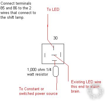
Text on the right reads: Existing LED wire, this end to alarm brain. Install a diode across the coil of the relay. Banded end of the diode on the positive wire. Non banded end on the wire that goes closer to ground when the lamp illuminates.
Posted By: micrors4racer
Date Posted: August 24, 2010 at 9:35 PM
Thanks I'll try it out. I don't need diodes to stop the 12v from going into the alarm brain or from the alarm brain to the shiftlight circuit? And when you mean existing LED wire do you mean the positive? Can I use a 1k ohm 1/2 watt resistor?
Posted By: i am an idiot
Date Posted: August 24, 2010 at 9:56 PM
The diode is only to protect your LED and your shift light output from the backlash of the relay coil. It will probably be OK without one, but in case you have not yet figured out, I really do not want any of your equipment to fail on my watch. Yes a 1/2 watt resistor will be twice as relaiable than a 1/4 watt device.
Posted By: micrors4racer
Date Posted: August 24, 2010 at 10:08 PM
Yes I understood the function of the diode on the coil thanks for always coming up with safe diagrams. I will try this now. I hate reading color bands on resistors as I am color blind haha
Posted By: i am an idiot
Date Posted: August 24, 2010 at 10:29 PM
Brown Black Red. anything above 680 Ohms should be OK. Anything from 680 to 3K will probably yield full brightness.
Posted By: micrors4racer
Date Posted: August 24, 2010 at 11:11 PM
Thanks for all the help man, it works beautifully!
|