single switch, multiple outputs
Printed From: the12volt.comForum Name: Relays
Forum Discription: Relay Diagrams, SPDT Relays, SPST Relays, DPDT Relays, Latching Relays, etc.
URL: https://www.the12volt.com/installbay/forum_posts.asp?tid=123522
Printed Date: May 09, 2026 at 2:37 AM
Topic: single switch, multiple outputs
Posted By: blowndakrt
Subject: single switch, multiple outputs
Date Posted: September 14, 2010 at 11:59 PM
Ok, Kind of have a weird idea, but not sure if there is an easier way to do it, or if I will have to use a bunch of relays.
I have a customer that added after market power windows to his car. He has 2 momentary rocker switches (ON)-Off-(ON), but wants to be able to use those same switches to control other things in his car. I tried to figure out how to go about it using a 3 position ON-Off-ON rocker. The problem I keep running into is that when the latched rocker is in the off position, for the power windows to work as normal.
The other part that I would like to find an easier method for is cutting down on the number of relays for the whole thing. If it is possible.
So basically what he wants to do is have the latched 3 way rocker be in the off position, power windows are controlled by the momentary rockers, but when he switches the latched 3 way rocker to ON in one direction, he can control his 2 linear actuators forward and backwards through the window switches. Then with the latched 3 way rocker in the other ON position, to control his air bags.
So a total of 3 rockers to control 6 different things. 2 momentary rockers and 1 latched 3 way rocker.
Is it possible, and what would be the best way to go about it?
Thanks for any advice or input.
Shawn
Replies:
Posted By: oldspark
Date Posted: September 15, 2010 at 12:24 AM
So you are saying the 3 position momentary "normally" controls ONE window up or down.
With the other 3-way on (one way), the momentary controls linear actuator fwd & back, and...
With that "other 3-way" on (the other way ), the momentary controls air bags up & down.
If that's correct, then pending a logic check......:
The latching 3 way could simply select which target is grounded; the momentary supplies power to all targets; and because the latching is centre-off, the ground selection is via 2 series SPDT relays with both 30-87a to the window motors; the relay's coils (85/86) to either "on" (actuator or bags) and its 87 to the target ground (actuator or bags).
And because of those "grounding" relays, that latching rocker can switch either hot or gnd (ie, to 86 or 85).
So that's 2 SPDT relays assuming the momentary rocker handles full power. Otherwise add 2 more relays (SPST unless braking is required).
Posted By: blowndakrt
Date Posted: September 15, 2010 at 8:19 AM
Correct, the momentary switches that are in there now control the windows up or down.
The part that I still down understand is when the latching 3 way is off, to keep the windows working. When you say ground selection is via 2 series SPDT relays, do you mean 2 relays wired in series? I am not understanding that part.
Also, if I use the relays as grounding, and the latched 3 way in is ON in either direction, does that stop the momentary from still operating the windows?
Thanks
Shawn
Posted By: oldspark
Date Posted: September 15, 2010 at 8:57 AM
Ok - it's a bit late (here) and it may need a diagram...
But Englishly speaking...
The "normal" situation is windows.
There are TWO series NC relays in the windows ground path. (IE -
neither relay energised, windows motors are grounded.)
If the latching on-off-on is in either ON position, it pulls in the respective relay above (hence breaking window ground) and connects/swaps its ground to the actuator else bags.
Meanwhile, the momentary 3-position when ON provides power to all 3 (windows, actuators & bags) but only ONE of them is grounded.
Makes sense?
(It does to me in Inglish, and head-logic etc, but I have yet to draw reality.... hence logic confirmation was sought. But I'm sure anyone hereon that sees the flaw will allow me to rope myself... (LOL!)).
Like I wrote - it's late... And I experienced a strange phenomenon earlier... physical exertion!
Posted By: blowndakrt
Date Posted: September 15, 2010 at 9:40 AM
I get what you are saying about the momentary supplying power to everything and use the relays to select which ones will see ground.
Just can't grasp how it would need to be wired up. A diagram would be great.
Will a simple 3 terminal latched rocker be ok for this, or will I need to use one with more terminals?
Cause the way I see the latched switch being wired, is center terminal goes to ground. Then the outer 2 terminals would go to the ground for the relays to run the 2 different parts (actuators and bags). Or will I need another relay between the ground for the center terminal for the power window relays?
I keep drawing out different configurations, but might be confusing myself even more. Maybe I am over thinking this and missing the simple way to do it.
I think I will wait till you get some free time and some rest to draw up a diagram. Maybe that will make more sense to me. LOL.
Thanks for the input and help.
Shawn
Posted By: oldspark
Date Posted: September 16, 2010 at 3:20 AM
Ok - it's rough and probably too big (I hate images that expand page margins!)
And the catch is that without diodes (or other decoupling), whichever side is ON will also pass power through the other two loads and it's own unused grounded side... (just follow the example below...)
EG - assume that instead of diodes, connections are straight thru:
With "window" selected as shown (relays off), assume the top rocker is "UP".
+12V then passes thru the RHS window motor and is grounded thru the relays. That's cool.
But +12V also goes thru the RHS "Bags" and LHS Bags up to the LHS "Down" rail, the thru the LHS Window which is grounded.
The same for the Actuator path.
And the same happens for any grounded "target" - ie, in parallel with the actuated & grounded target (window or bags or actuator; up or down etc) with be BOTH other circuits (in parallel) with the target's opposite non-actuated but grounded half.
But the diagram is "conceptual" only - ie, it describes operation rather than implementation....
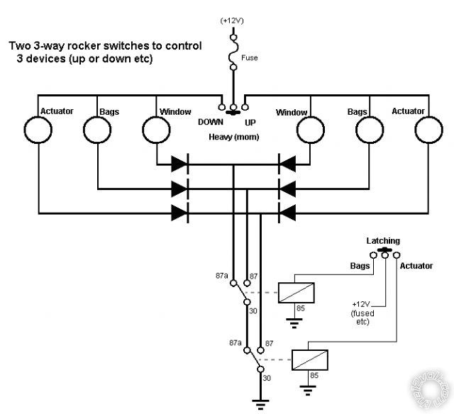
For example, if the "power" (upper) rocker can't handle the current, relays are required.
If the devices are not separate +12V windings or terminals, then alternate switching is required (eg - if +12V & GND are reversed and not merely +12V as shown).
And I do not like using diodes for "power" things - but up to 3A is usually ok. Above that, relay switching may be better.
Before getting in to better design I figured I'd merely post the above....
Maybe 6 relays are required.... (SPDT else DPDT etc)
And as I am about to order some FETs, I can't help but ponder... (Most prefer relays to "electronic components" like FETs & transistors. But with these MOSETS costing a mere $2.50 each; being the size of a thumbnail; capable of switching 60A-110A at kilo-Hz and merely requiring nano-Amps to turn on (with maybe 1 else 2 resistors per FET)... and silent operation....)
Anyhow, what's the highest current involved?
And are all devices "reversed" with polarity or an extra winding? (And which has which?)
PS - not that I like the energised relays above if left in bags or actuator position...
And the catch is that without diodes (or other decoupling), whichever side is ON will also pass power through the other two loads and it's own unused grounded side... (just follow the example below...)
EG - assume that instead of diodes, connections are straight thru:
With "window" selected as shown (relays off), assume the top rocker is "UP".
+12V then passes thru the RHS window motor and is grounded thru the relays. That's cool.
But +12V also goes thru the RHS "Bags" and LHS Bags up to the LHS "Down" rail, the thru the LHS Window which is grounded.
The same for the Actuator path.
And the same happens for any grounded "target" - ie, in parallel with the actuated & grounded target (window or bags or actuator; up or down etc) with be BOTH other circuits (in parallel) with the target's opposite non-actuated but grounded half.
But the diagram is "conceptual" only - ie, it describes operation rather than implementation....
For example, if the "power" (upper) rocker can't handle the current, relays are required.
If the devices are not separate +12V windings or terminals, then alternate switching is required (eg - if +12V & GND are reversed and not merely +12V as shown).
And I do not like using diodes for "power" things - but up to 3A is usually ok. Above that, relay switching may be better.
Before getting in to better design I figured I'd merely post the above....
Maybe 6 relays are required.... (SPDT else DPDT etc)
And as I am about to order some FETs, I can't help but ponder... (Most prefer relays to "electronic components" like FETs & transistors. But with these MOSETS costing a mere $2.50 each; being the size of a thumbnail; capable of switching 60A-110A at kilo-Hz and merely requiring nano-Amps to turn on (with maybe 1 else 2 resistors per FET)... and silent operation....)
Anyhow, what's the highest current involved?
And are all devices "reversed" with polarity or an extra winding? (And which has which?)
PS - not that I like the energised relays above if left in bags or actuator position...
Posted By: i am an idiot
Date Posted: September 16, 2010 at 7:16 AM
This rotary switch would allow the switches to be used for up to 6 different devices.

Posted By: blowndakrt
Date Posted: September 16, 2010 at 10:48 AM
oldspark wrote:
Ok - it's rough and probably too big (I hate images that expand page margins!)
And the catch is that without diodes (or other decoupling), whichever side is ON will also pass power through the other two loads and it's own unused grounded side... (just follow the example below...)
EG - assume that instead of diodes, connections are straight thru:
With "window" selected as shown (relays off), assume the top rocker is "UP".
+12V then passes thru the RHS window motor and is grounded thru the relays. That's cool.
But +12V also goes thru the RHS "Bags" and LHS Bags up to the LHS "Down" rail, the thru the LHS Window which is grounded.
The same for the Actuator path.
And the same happens for any grounded "target" - ie, in parallel with the actuated & grounded target (window or bags or actuator; up or down etc) with be BOTH other circuits (in parallel) with the target's opposite non-actuated but grounded half.
But the diagram is "conceptual" only - ie, it describes operation rather than implementation....
For example, if the "power" (upper) rocker can't handle the current, relays are required.
If the devices are not separate +12V windings or terminals, then alternate switching is required (eg - if +12V & GND are reversed and not merely +12V as shown).
And I do not like using diodes for "power" things - but up to 3A is usually ok. Above that, relay switching may be better.
Before getting in to better design I figured I'd merely post the above....
Maybe 6 relays are required.... (SPDT else DPDT etc)
And as I am about to order some FETs, I can't help but ponder... (Most prefer relays to "electronic components" like FETs & transistors. But with these MOSETS costing a mere $2.50 each; being the size of a thumbnail; capable of switching 60A-110A at kilo-Hz and merely requiring nano-Amps to turn on (with maybe 1 else 2 resistors per FET)... and silent operation....)
Anyhow, what's the highest current involved?
And are all devices "reversed" with polarity or an extra winding? (And which has which?)
PS - not that I like the energised relays above if left in bags or actuator position...
Well the valves for the bag controls I do know are grounded already, and simply need a positive pulse to activate. So if the diagram you pictured will still have 12 volts going to it when its in another rocker position, the valves will be activated. Not that it matters, but we will be doing front and rear bags instead of RHS and LHS.
The relays shown in your diagram, are those the ones that are already there to control the power windows, or are those additional? Reason being, I would like to keep from doing anything to those relays. Its actually a small control module he has installed. I am sure its just a box with relays in it, but don't want to affect the lifetime warranty of his module by tampering with it. And would also like them to be isolated with another relay to prevent causing damage to the switch. I am going to assume that all of the amperages will not be around 10-15 amps each direction on the switch (aside from the power windows), but can't be sure depending on load if he tries to run both switches at the same time. So just want to be safe and protect the window module and switches form anything I hook up, again to protect his warranty.
I would prefer that the other devices not be seeing power all the time. Even if that means more relays. All feeds would be ignition based rather than 12 V constant, so not worried about them draining the car when its off, but I am with you about having all of them resting at 12 volts. I do know he is wanting to add the power windows to an alarm system as well, so don't want to run into an issue where he leaves the switch in the 1 or 3 position and activates his other devices instead of the windows. I would assume I can tie the alarm module down stream to the power windows and use a diode on the wires from the switch to the motor so it only operates the windows, no matter what position the switch is left in.
As far as the the other electronics, that is way out of my league of understanding. LOL. I still have a tough time grasping the different configurations of relays to do what I want. Hence this posting. Haha. But if someone more knowledgeable than me wanted to build something to do this exact thing more efficiently, I would be willing to pay for the materials and their time. As long as its not going to be expensive. LOL.
I was looking at relay control boards, but it seems all the ones I could find need to be operated from a PC/serial source. Again above my knowledge level.
So does the added info affect the diagram greatly? I realize it probably adds twice the relays to the diagram. In my head, I was thinking of doing 3 relays coming off the latched rocker. When it was in postion 1, I would need to cut power to the other 2 relays, and vice versa for each position of the latched rocker. That way only the device selected would be getting power. I am not sure how to do that with relays. When one turns on, others shut off.
Thanks greatly for the help. Seeing the diagram really cleared up what you were talking about.
Shawn
Posted By: blowndakrt
Date Posted: September 16, 2010 at 10:55 AM
The problem with the rotary switches is the size and the look. I was hoping to just add a 3 rocker to his setup to keep it all flowing as far as the look. And he would like something that is easily accessible, so mounting a rotary switch elsewhere would take away from that.
But I do appreciate the help. Keep it coming. I am open to all sorts of ideas if we can come up with a solution that works for the customer as well.
Shawn
But I do appreciate the help. Keep it coming. I am open to all sorts of ideas if we can come up with a solution that works for the customer as well.
Shawn
Posted By: oldspark
Date Posted: September 16, 2010 at 5:37 PM
Plus the rotary still needs some form of selection/activation button....
For the system above, interception is required on both hot & grounded sides - ie, the bag valves grounding needs to be cut & relayed.
But the same occurs for anything that uses polarity changeover instead of an extra winding/terminal to reverse direction - eg, window up & down. (Most windows I know of are a two-wire motor whose polarity is simply reversed to change direction.)
As to what the above relays are - that's up to you, though relays usually aren't required to switch other relays except for extra control logic or for high current relays (solenoids).
But from what you say, it sounds like six relays are required where the rockers merely select which individual relay is activated at any time.
The relay types depend on the connection required - ie, 2 SPDT for window polarity change over; 2 SPST for the air bags; and 2 whatever (SPST or SPDT) for the actuator.
(In practice I'd use all SPDT - they are usually the same price, and can then be swapped if a NC contact (87a) burns out. IE - one size fits all; standard 15A or 30A SPDT "changeover" relays.)
The only additional aspect is the window control.
Since the device-selection rocker is 2-pole and not 3-pole, the window is selected by default (as in my diagram - the grounding relays) and selection of either of the others DESELECTS the window.
That can be done with 2 diodes and an extra relay, or two extra relays.
Your choice?
It may be possible to reduce the number of relays depending on the actuator wiring (polarity changeover, or 2 wires plus hot or ground?), or if diodes etc are implemented (though I'd limit that to "logic" level only and use relays for all the power switching).
Posted By: i am an idiot
Date Posted: September 16, 2010 at 7:58 PM
The momentary switches will not handle the current needed by the bag valves. You will have to use a relay on each set of valves. Set = all 4 raise valves. or pair of raise valves if you wish to raise front and rear independently. I did not read much of what was posted after my last, Spark may have already covered this.
Posted By: oldspark
Date Posted: September 16, 2010 at 10:40 PM
I can see why the rotary is out...
Selection is too inconvenient - ie, dial one of 6 positions, then hit the "go" button. (Or dial one of 3, then rocker the right direction for go.)
Rockers don't need sighting...
Selection is too inconvenient - ie, dial one of 6 positions, then hit the "go" button. (Or dial one of 3, then rocker the right direction for go.)
Rockers don't need sighting...
Posted By: blowndakrt
Date Posted: September 17, 2010 at 1:06 AM
oldspark wrote:
Plus the rotary still needs some form of selection/activation button....
For the system above, interception is required on both hot & grounded sides - ie, the bag valves grounding needs to be cut & relayed.
But the same occurs for anything that uses polarity changeover instead of an extra winding/terminal to reverse direction - eg, window up & down. (Most windows I know of are a two-wire motor whose polarity is simply reversed to change direction.)
As to what the above relays are - that's up to you, though relays usually aren't required to switch other relays except for extra control logic or for high current relays (solenoids).
But from what you say, it sounds like six relays are required where the rockers merely select which individual relay is activated at any time.
The relay types depend on the connection required - ie, 2 SPDT for window polarity change over; 2 SPST for the air bags; and 2 whatever (SPST or SPDT) for the actuator.
(In practice I'd use all SPDT - they are usually the same price, and can then be swapped if a NC contact (87a) burns out. IE - one size fits all; standard 15A or 30A SPDT "changeover" relays.)
The only additional aspect is the window control.
Since the device-selection rocker is 2-pole and not 3-pole, the window is selected by default (as in my diagram - the grounding relays) and selection of either of the others DESELECTS the window.
That can be done with 2 diodes and an extra relay, or two extra relays.
Your choice?
It may be possible to reduce the number of relays depending on the actuator wiring (polarity changeover, or 2 wires plus hot or ground?), or if diodes etc are implemented (though I'd limit that to "logic" level only and use relays for all the power switching).
Well I haven't started collecting any parts yet. So if it would be easier with a different latching switch, I can probably do that. Would I need to go with a DPDT latching rocker instead, or what kind of latching rocker would I need to use to help simplify this? And according to the switch drawing, the one I was looking at is listed as a 3P SPDT rocker. Is that not a true 3 pole switch, but merely a 3 terminal switch?
I would like to not have to use a relay on both the positive and negative leads to the valves, but simply a relay on the positive side. All the valves are grounded at the valve mounting, so it would be a complete rewire of all his valves to be able to do that.
Thanks
Shawn
Posted By: oldspark
Date Posted: September 17, 2010 at 2:38 AM
With the rocker, you are using 3 positions to control 3 things so that has little alternative - unless you want a 4 position switch 3 ONs & 1 OFF)
But before anything more, please confirm your wiring:
The window is polarity reversal to change direction.
The bags are grounded with a +12V "switch"; one for front, one for back (raise or lower irrelevant - only one thru the rocker).
How is the actuator wired for up/down, in/out whatever.
BTW - no need to switch the bag grounds. Keep in mind, we will now use individual relays, not the arrangement shown in my diagram.
And rocker are the best because no interlocking is required.
Posted By: blowndakrt
Date Posted: September 17, 2010 at 12:22 PM
oldspark wrote:
With the rocker, you are using 3 positions to control 3 things so that has little alternative - unless you want a 4 position switch 3 ONs & 1 OFF)
But before anything more, please confirm your wiring:
The window is polarity reversal to change direction.
The bags are grounded with a +12V "switch"; one for front, one for back (raise or lower irrelevant - only one thru the rocker).
How is the actuator wired for up/down, in/out whatever.
BTW - no need to switch the bag grounds. Keep in mind, we will now use individual relays, not the arrangement shown in my diagram.
And rocker are the best because no interlocking is required.
I will have him bring the car in this weekend and take a look at the windows.
I do know for a fact that the valves are positive pulse to activate, as they are grounded individually at each valve mount.
As far as the actuators, I will also double check those as well.
He did mention that he could possibly be talked into 3 small momentary push buttons instead of the rocker, but wanted to be able to just go from one button to the next, and the previous momentary would be turned off. But that would require another 4 relays per push button to do on top of another 3 relays to give the second output for the devices. So in my head that is 15 relays. WOW. Think I will stick to the rocker idea for now. Haha.
Thanks
Shawn
Posted By: oldspark
Date Posted: September 17, 2010 at 1:15 PM
I reckon stick with the rockers.
As I said, there are no interlock issues if you do.
Besides, holding 2 switches isn't good (unless you intend using the latching rocker as up/down etc) - it'd probably be better with 6 buttons
I doubt that you'd need 15 relays - probably use DPDTs instead of SPST/SPDT. But that all depends on the actuators. (The windows would need 3PDT else dual relays etc.)
And that's where I think relay logic gets ridiculous - eg 15 relays instead of 6 relays and some electronics. But that's me....
Posted By: blowndakrt
Date Posted: September 17, 2010 at 1:20 PM
oldspark wrote:
I reckon stick with the rockers.
As I said, there are no interlock issues if you do.
Besides, holding 2 switches isn't good (unless you intend using the latching rocker as up/down etc) - it'd probably be better with 6 buttons
I doubt that you'd need 15 relays - probably use DPDTs instead of SPST/SPDT. But that all depends on the actuators. (The windows would need 3PDT else dual relays etc.)
And that's where I think relay logic gets ridiculous - eg 15 relays instead of 6 relays and some electronics. But that's me....
I agree. And from an ease of use and cosmetic standpoint, the rocker is going to be the way to go. Less parts is less chance something can go wrong. And easier to diagnose and replace parts if a relay wears out.
Shawn
Posted By: blowndakrt
Date Posted: September 17, 2010 at 1:42 PM
i am an idiot wrote:
The momentary switches will not handle the current needed by the bag valves. You will have to use a relay on each set of valves. Set = all 4 raise valves. or pair of raise valves if you wish to raise front and rear independently. I did not read much of what was posted after my last, Spark may have already covered this.
The coils are 8 watts, so only draw around .70 amps to operate. But I did plan to use a relay anyways.
Thanks
Shawn
Posted By: oldspark
Date Posted: September 17, 2010 at 9:20 PM
If they are under an amp, why use relays if not needed?
Though relays are VERY reliable, it is still extra failure points etc.
And for that current, I definitely think it worthwhile understanding and using diodes! (EG - a small 2-terminal IN4004 costing 20c instead of a 4 terminal $2-$5 relay; or a few to replace 8 terminal DPDT relays etc.)
Though relays are VERY reliable, it is still extra failure points etc.
And for that current, I definitely think it worthwhile understanding and using diodes! (EG - a small 2-terminal IN4004 costing 20c instead of a 4 terminal $2-$5 relay; or a few to replace 8 terminal DPDT relays etc.)
Posted By: blowndakrt
Date Posted: September 17, 2010 at 11:49 PM
oldspark wrote:
If they are under an amp, why use relays if not needed?
Though relays are VERY reliable, it is still extra failure points etc.
And for that current, I definitely think it worthwhile understanding and using diodes! (EG - a small 2-terminal IN4004 costing 20c instead of a 4 terminal $2-$5 relay; or a few to replace 8 terminal DPDT relays etc.)
Well I figured I would have to use relays to allow the "switching" so to speak to the different devices. What else would turn off the signal going to the valves when the rocker is in the other position to control the actuators or windows?
Shawn
Posted By: oldspark
Date Posted: September 18, 2010 at 12:22 AM
I was considering more from the control POV - ie, you shouldn't need more than the 6 relays that switch the power - the logic is done by novel interconnection (eg - the 2 series-grounding relays in my earlier diagram) and maybe diodes.
(Remember - the diodes in my diagram were not "logic" or control diodes, they were to stop "leakage" thru alternate paths. If the loads were LEDs or similar impedances requiring full voltage, they would not be required.)
But a lot depends on the topology.
For example, to "OR" three inputs (either a or b or c turn on the load), in addition to the 3 switches, 3 relays or 3 diodes are needed if it is hot switched (+12V).
But if it is ground switched, only the 3 switches are needed (they are all commoned to ground instead of (different) +12V sources.
FYI - It does seem to annoy people when I replace their complex multiple relays with a polarity change of the control switching and maybe retain 1 or 2 of their birds-nested relays! But I blame that on psychologists and their Bool.
Posted By: blowndakrt
Date Posted: September 19, 2010 at 11:58 AM
Ok, I was able to take a look at the car again and get some info.
For the windows, its seems I am not getting 12 volts at the switch themselves, but I do get 12 volts coming out of the small control box that goes to the window motors. So I will probably make my connections after that small control box. That way I can be sure I am getting a full 12 volts to the relays and don't have to worry about affecting the warranty of the control box.
He also brought in the wiring instructions for the power window kit the shop installed. They have a pre-terminated plug on each end that plugs into the window switches and then into that small control box. Since I am not getting a full 12 volts from the switch, I am going to assume they are using data or possibly USB protocol to the control box. Then coming out of the control box, it has the power, ground for the control box, and then the wires going out to the window motors.
Blue/Green - LF Up (AC)
Blue/Black - LF Down (AC)
Green - RF Up (AC)
GREEN/ Black - RF Down (AC)
WHITE/ Green - LR Up (AC)
WHITE/ Black - LR Down (AC)
ORANGE / Green - RR Up (AC)
ORANGE / Black - RR Down (AC)
Edit: After re-reading, figured I should clarify the above wires. He is not using all 4 windows. He is only using the fronts. I am assuming they send out the same control box for the 2 window kits and the 4 window kits. But his kit only has the 2 window switches.
So I'm thinking that they put (AC) in the diagram to show polarity switching. Would that be correct? I tested each wire they get 12 volts when you hit the rocker in that direction.
For the air bag valves, each valve is getting 12 V momentary to operate out of the switch box. He wants to keep the switch box hooked up as well as it has built in remote control functions. So I am going to assume we will need to use a diode on those so he doesn't accidentally operate another feature through the remote if the switch is not set to that operation.
Now the weird part is the actuators. One is seeing a 12 V momentary for the forward movement and 12 V momentary for the retract movement. That is the hood actuator.
The trunk actuator is seeing a momentary negative pulse for forward movement, and momentary negative pulse for retract. This is because he is using a small actuator controller with programmable stops on both directions. So a single negative pulse on one wire opens the trunk to the predetermined stop, and then a negative pulse on the other wire closes the trunk to the predetermined stop.
He said the shop did it that way because the actuator they used has too much travel, but had to use that size for the weight. Plus they told him it would make it simple to add a trunk pop feature when he installed his alarm later on. Which I agree with.
So with that info, is this going to make the relays and such much more complicated?
Thanks
Shawn
Posted By: oldspark
Date Posted: September 19, 2010 at 12:55 PM
Que?
It seems we now have 4 windows instead of one....
You supply a connection diagram of how it it currently configured, plus what you want to control the relays and where those relays are to be added.
We'll take it from there....
It seems we now have 4 windows instead of one....
You supply a connection diagram of how it it currently configured, plus what you want to control the relays and where those relays are to be added.
We'll take it from there....
Posted By: i am an idiot
Date Posted: September 19, 2010 at 1:13 PM
I think Radio Shack sells a 6 position Double pole rotary switch. I can get you a part number if youi need it.
Posted By: blowndakrt
Date Posted: September 19, 2010 at 3:38 PM
oldspark wrote:
Que?
It seems we now have 4 windows instead of one....
You supply a connection diagram of how it it currently configured, plus what you want to control the relays and where those relays are to be added.
We'll take it from there....
Yeah after I went back and reread what I had typed, I edited the post to show that we were only using the front windows on his setup. I simply copied exactly what they had on the wire diagram that came with the window kit.
I want to put the relays on the output of the window control box.
Those wires all have 12 volts momentary.
Blue/Green - LF Up (AC)
Blue/Black - LF Down (AC)
Green - RF Up (AC)
GREEN/ Black - RF Down (AC)
The windows control will be with the latched rocker in the off position.
With the latched rocker in the 1st On position, the 2 switches will simply be momentary 12v to go to the air bag valves.
With the latched rocker in the 2nd On position, one of the window switches , we will say left for example, (up/down) will be momentary 12v for the front hood actuator. The other window switch, we will say right, will be momentary negative (up/down) for the rear actuator going to the actuator control box.
If needed, I can simply do another set of relays to convert to negative polarity for the trunk actuator. But figured I would give the info exactly how it is setup, so that if we can do the negative polarity for the right switch, when in 2nd on position, by wiring up that set of relays different, you would have the info before hand.
Does that make sense?
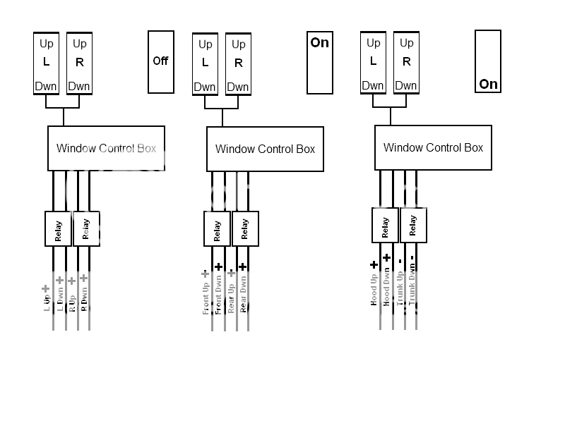
Here is a quick picture I drew up to show where I want to go with the relays. There are 3 different pictures there to show how I would like each output from the relays with the latched rocker position. It shows the 2 window rockers as well as the latched rocker in the different positions.
I realize it will be more than 2 relays in the total configuration, but just drew 2 for each output to keep it from being cluttered.
Hope that helps convey what I am trying to acheive.
Thanks
Shawn
Posted By: oldspark
Date Posted: September 19, 2010 at 8:45 PM
The diagram is good.
Just add the the "target" (motors, actuators, valves) with their connections and grounding; and which switches you are adding or using, and how they are powered.
You don't have to worry about the existing window switches if they are not being used. (Although why NOT use the window control box?)
This is very different to what you originally which only involved 3 individual targets.
Make sure you clarify how many windows are being controlled - it was ONE window up/down, bags front/rear, and actuator hood/trunk.
Posted By: blowndakrt
Date Posted: September 19, 2010 at 10:50 PM
oldspark wrote:
The diagram is good.
Just add the the "target" (motors, actuators, valves) with their connections and grounding; and which switches you are adding or using, and how they are powered.
You don't have to worry about the existing window switches if they are not being used. (Although why NOT use the window control box?)
This is very different to what you originally which only involved 3 individual targets.
Make sure you clarify how many windows are being controlled - it was ONE window up/down, bags front/rear, and actuator hood/trunk.
Sorry, I may have confused you as we went back on forth on some ideas.
In my original post I talked about a set of aftermarket power windows in the vehicle. He wanted to use a separate 3 way latched rocker to allow the factory power window switches to control the other devices.
From my original post "I have a customer that added after market power windows to his car. He has 2 momentary rocker switches (ON)-Off-(ON), but wants to be able to use those same switches to control other things in his car. I tried to figure out how to go about it using a 3 position ON-Off-ON rocker. The problem I keep running into is that when the latched rocker is in the off position, for the power windows to work as normal."
So in essence, we would only be adding a single 3 way latched rocker to his current setup.
My original idea was to put the relays after the power window control box. For one, because I know I am getting 12 volts out of that, and to protect the warranty on his power window kit. Plus the entire idea was to not clutter up the car with more switches. So we were just looking to add the single 3 way latched rocker and use the switches that are already in there for the power windows to control everything.
I just assumed in your diagram you were showing the wiring for a single momentary rocker and I would need to duplicate that for the other switch.
In the diagram I posted, the first one is going to go for the power windows, Left up, Left down, Right Up, Right down. Since the power windows are reversed polarity, it will depend on which direction the motor is going as to which is power and which is ground.
The second diagram is for the air bags. I need a positive momentary that is active as long as the button is held down in the desired direction to activate them as they are grounded at the valve mounts already. Like I said before, I do not want to use the relay on the grounds as it would mean a complete rewire of his entire air system.
And finally the last one is to the linear actuators. For the one actuator I need a positive momentary to the extend wire, and then a positive pulse for the retract wire. Both of those will need to be active as long as the button is held down in the desired direction. I do not need to have them switch polarity.
For the other actuator, I would need a negative momentary for both wires. It does not matter if it is a single pulse or a negative momentary that is active as long as the button is pressed. The actuator controller will work the same with either negative input.
Shawn
Posted By: blowndakrt
Date Posted: September 20, 2010 at 10:40 AM
Here is the picture with the added devices and how they are hooked up.
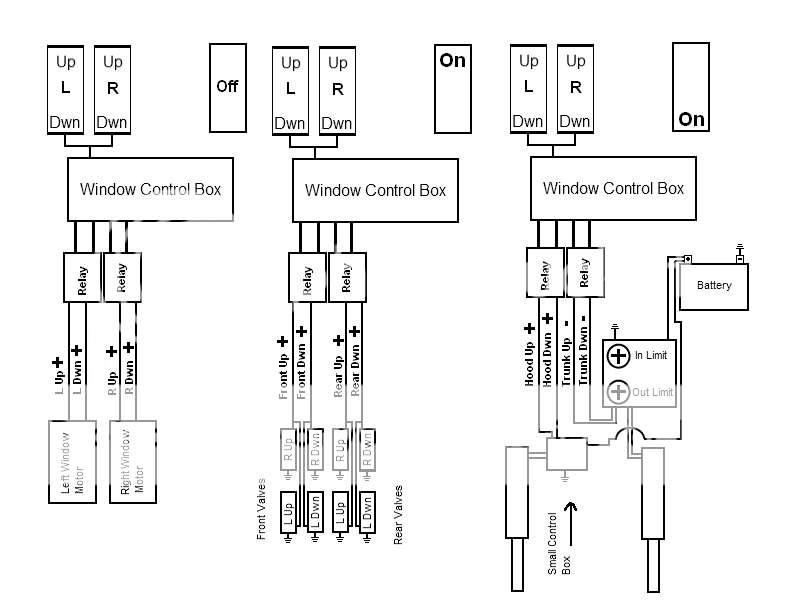
Thanks
Shawn
Thanks
Shawn
Posted By: blowndakrt
Date Posted: September 22, 2010 at 9:40 AM
So anymore info or ideas on this? Is it going to be possible?
Thanks
Shawn
Thanks
Shawn
Posted By: oldspark
Date Posted: September 22, 2010 at 10:43 AM
Sorry - I thought there was more coming....
So.... you will add a rocker switch.
In its neutral position (off), windows operate normally.
In one position (on1) the valves are selected (instead of windows).
In the opposite position (on2) the actuators are selected.
The "pulsing" required is down by the switch operator.
As you have drawn it, the valves are easy.
A DPDT relay for each end (1 front, 1 rear) placed "between" the window motors and the valves.
Contacts #30 to the Window Control Box.
Contacts #87a (NC) to window motors.
Contacts #87 to valves.
Both relay #85s to GND.
Both relay #86s to the added rocker switch's "on1".
The same should apply to the actuators (not that the window motors are shown with them).
Hence 4 DPDT relays.... ??
Posted By: blowndakrt
Date Posted: September 22, 2010 at 1:03 PM
oldspark wrote:
Sorry - I thought there was more coming....
So.... you will add a rocker switch.
In its neutral position (off), windows operate normally.
In one position (on1) the valves are selected (instead of windows).
In the opposite position (on2) the actuators are selected.
The "pulsing" required is down by the switch operator.
As you have drawn it, the valves are easy.
A DPDT relay for each end (1 front, 1 rear) placed "between" the window motors and the valves.
Contacts #30 to the Window Control Box.
Contacts #87a (NC) to window motors.
Contacts #87 to valves.
Both relay #85s to GND.
Both relay #86s to the added rocker switch's "on1".
The same should apply to the actuators (not that the window motors are shown with them).
Hence 4 DPDT relays.... ??
Not sure what you mean by the window motors are not shown with them.
I wasn't sure how to draw it up with everything all in one drawing since I wasn't sure how many relays it was gonna take. But I can change the drawing to reflect all the devices coming out of the window control module and just draw in a couple of boxes to simulate the relay pack.
I did the drawing up to show 3 different scenarios. All of these will be controlled by the same 2 rocker switches for the windows. It will just depend on which direction the latched rocker (3rd rocker pictured) will be in as to which set of pictures it will branch out from out of the window control module.
Here it is redrawn.
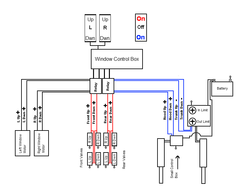
I realize it only shows 2 relays, but think of those 2 as the block of relays that will be needed.
The different colors show the direction of the rocker, and what the corresponding devices will be operating. Red On, will be going to the valve assembly, Black Off will be controlling the power windows, and Blue On will be going to the actuators.
Does this make more sense, or do I need to redraw it a different way? Just trying to be clear as to what I want the final outcome to be.
Thanks
Shawn
Posted By: oldspark
Date Posted: September 23, 2010 at 3:53 AM
Ah! I thought the "upper" valves were window motors... d'oh!
Damned people and their interpretations...
Like how stupid would you be if you interpreted the "three scenarios" to be three time-shifted depiction from left to right?
Of course you wouldn't know because you drew it in "real time" with the three "systems" from left to right!
I never would have expected such a logical or obvious layout.
Your are devious - you must know the sorts of diagrams I put up with.
NOTE! I am having fun. And it is a MY expense - NOT yours.
(Just in case OPs think I am having a go at them as some poor OP from UAE did recently when a replier (also) LOL'd at his (IMO) humorous(?) depiction of "words to his contractors". Another non-existent problem that flamed into the bit bucket....)
Now having wasted another half a page....
And having reconsidered...
... and eaten egg....
GREAT! Even better!
Now, until I get to putting this diagramatically ....
Picture each of your "Relay" as being two relays - one under the other. Hence 2x2 relays = 4 total.
Each relay is DPDT - ie 2 pole changeover.
The top relay's NC contact #87a connects to the next (under) relay's input (#30), and its NO #87 goes to valves.
Hence if the top relay is energised the WCB (Window Control Box) output is diverted to the valves.
Otherwise....
The bottom relay is similarly connected with NO (Normally Open) #87 to the actuator/s, and its NC #87a to the windows.
Hence with the lower relay energised, the WCB output goes to the actuators.
If neither relay is actuated, the WCB output is connected to the windows (thru Normally Closed NC contacts #87a).
Now, 4 relays.
The upper 2 are for (say) valves.
The lower 2 are (thus) for actuators.
The 2 left-side relays are (say) for LHS window or front valves or bonnet... er, hood.
The 2 right-side relays are (this) for RHS window or rear valves or boot... er, trunk.
Obviously..... the assigning of left to front or rear is subject to your local convention else is arbitrary.
But the front valve should IMO be the same window-switch direction as front actuator hood/bonnet.
And we should all know that boots are up the rear! (That's another LOL...?)
And each relay has 2 poles - one for up, & one for down signals from the WCB.
Else 2 SPDT repays could be used with their coils (#85 & #86) in parallel.
So 4x DPDT else 8x SPDT relays as far as simple "switch decoding" and "up/down" to each of the targets goes.
I like it.
But it seems too simple. What a I missing.... (Forget "pulses" etc - that's separate.)
But this is an extension of my original diagram which uses hot switching instead of GND switching (and where relays negate the use of blocking diodes). (It also demonstrates how GND switching or Open-Collector outputs or "inverted logic" can greatly simplify circuitry.)
And no diodes are required - unless coil-spike suppression is required, but it shouldn't be since the WCB control motors; maybe using relays itself?
So Mr Smarty Boot, tell me where I've gone wrong this time!

Now, I'll get to modifying your diagram....
[Warning - I use "circuits" rather than "relay housing" depictions. That's because I want to easily trace the connections & operation. (Plus I rarely use Hella/Bosch type relays!)]
Damned people and their interpretations...
Like how stupid would you be if you interpreted the "three scenarios" to be three time-shifted depiction from left to right?
Of course you wouldn't know because you drew it in "real time" with the three "systems" from left to right!
I never would have expected such a logical or obvious layout.
Your are devious - you must know the sorts of diagrams I put up with.
NOTE! I am having fun. And it is a MY expense - NOT yours.
(Just in case OPs think I am having a go at them as some poor OP from UAE did recently when a replier (also) LOL'd at his (IMO) humorous(?) depiction of "words to his contractors". Another non-existent problem that flamed into the bit bucket....)
Now having wasted another half a page....
And having reconsidered...
... and eaten egg....
GREAT! Even better!
Now, until I get to putting this diagramatically ....
Picture each of your "Relay" as being two relays - one under the other. Hence 2x2 relays = 4 total.
Each relay is DPDT - ie 2 pole changeover.
The top relay's NC contact #87a connects to the next (under) relay's input (#30), and its NO #87 goes to valves.
Hence if the top relay is energised the WCB (Window Control Box) output is diverted to the valves.
Otherwise....
The bottom relay is similarly connected with NO (Normally Open) #87 to the actuator/s, and its NC #87a to the windows.
Hence with the lower relay energised, the WCB output goes to the actuators.
If neither relay is actuated, the WCB output is connected to the windows (thru Normally Closed NC contacts #87a).
Now, 4 relays.
The upper 2 are for (say) valves.
The lower 2 are (thus) for actuators.
The 2 left-side relays are (say) for LHS window or front valves or bonnet... er, hood.
The 2 right-side relays are (this) for RHS window or rear valves or boot... er, trunk.
Obviously..... the assigning of left to front or rear is subject to your local convention else is arbitrary.
But the front valve should IMO be the same window-switch direction as front actuator hood/bonnet.
And we should all know that boots are up the rear! (That's another LOL...?)
And each relay has 2 poles - one for up, & one for down signals from the WCB.
Else 2 SPDT repays could be used with their coils (#85 & #86) in parallel.
So 4x DPDT else 8x SPDT relays as far as simple "switch decoding" and "up/down" to each of the targets goes.
I like it.
But it seems too simple. What a I missing.... (Forget "pulses" etc - that's separate.)
But this is an extension of my original diagram which uses hot switching instead of GND switching (and where relays negate the use of blocking diodes). (It also demonstrates how GND switching or Open-Collector outputs or "inverted logic" can greatly simplify circuitry.)
And no diodes are required - unless coil-spike suppression is required, but it shouldn't be since the WCB control motors; maybe using relays itself?
So Mr Smarty Boot, tell me where I've gone wrong this time!
Now, I'll get to modifying your diagram....
[Warning - I use "circuits" rather than "relay housing" depictions. That's because I want to easily trace the connections & operation. (Plus I rarely use Hella/Bosch type relays!)]
Posted By: oldspark
Date Posted: September 24, 2010 at 2:48 AM
I had a choice of reality or drawing. I chose the latter.
How's below...? I drew it as 8 SPDT relays but it could could be 4 DPDT or 2 QPDT.
I thinks it's self explanatory. If not - maybe read my previous reply...?
Diagramatically I swapped Valve & Window positions for simpler route layout, and I crossed-over the horizontal lines for the Lids (hood/trunk)...
As mentioned earlier, the rocker could ground switch "hot" relay coils, or +12V switch them as shown. No big deal; whatever suits.
I haven't shown fuse(s) or spike-quenching diodes (across the coils - they are probably not needed).
Normal wiring drawing rules apply - crosses or crossovers are NEVER joints; any joints are show as T's (not that there are any). LOL - I miss the old dots, but really appreciate the new convention.
I didn't match line widths, nor colours...
And rather than confustigate with added solenoid connections, I just drew the one, but all "valve" solenoids common/joined; likewise all "Lid" solenoids. IR - it looks like two separate solenoids only.... (whether 2 lots of one, 2 or 4 relays).
Any problems just ask. But if you find the Doh! glaring mistake I'm bound to find in about 3 minutes - forget it - yesterday's chance was missed! (LOL!)
Posted By: blowndakrt
Date Posted: September 24, 2010 at 8:30 AM
From your drawing, it looks as if the power from the latched rocker is going to the valves and the dotted line I am assuming it for the activation signal? Is that correct?
The valves are simply 2 wire feeds. You have your ground and then your 12 v push to make activation. Or is it just the way I am reading the diagram? Are what I am looking at as valves, actually relays?
Maybe I am over thinking this again and not fully following the diagram. I just want to make sure I am understanding the drawing before I ask any questions. No sense in asking if understanding the drawing as you drew it, would answer any questions I would be asking.
Thanks
Shawn
Posted By: oldspark
Date Posted: September 24, 2010 at 9:07 AM
Hee hee. LOL. Ha ha!
My fault? I forgot to say the dashed lines represent the "electromagnetic solenoid-to-contact" interaction.
IE - a solenoid pulls in the contact it is dashed to.
(And - by convention, de-energised is "away" from the solenoid since solenoids pull contacts TOWARDS them. But, if shown arse-about, that is understood and accepted.)
LOL - to think I took the trouble to show solenoids IN-LINE with their contacts... (Often they are remote and don't even include "bent" or zig-zag lines to make it obvious which solenoid for which contact - they just label (say) S1 and then "1a" and "1b" for the contacts; and S(olenoid)2 will have c2a & c2b or (Contacts) 2a & 2b etc.)
I thought it would be obvious. It is so well understood in my circles... (whereas the12volt's "physical" drawings stuffs me/us up completely! Plus 10%.)
Hopefully this is now "as obvious" to you as your drawing "became obvious" to me...
Does this/that make sense?
I will now re-read your last reply.....
WARNING: I will soon enter a religious period of comatose worship. Hence I may soon be unavailable until released from care, or someone posts bail. (If worse than that - fear not - I WILL channel!)
I am currently well into my pre-consumpotive practice session for said observance!
Posted By: blowndakrt
Date Posted: September 24, 2010 at 9:28 AM
Ok, I think I understand now.
So the 12v from the latched rocker will come into 85 with it in the first on position. 86 will be to ground. Output from the WCB will go to 87, and 87a will go to front valves. 30 will go down to the lower set of relays and connect to 87a, and 30 will go to window motor wires. 87 will go linear actuators. Then 85 will go to the 12v from the latched rocker in the second on position.
Is that correct? Or do I have 87 and 87a mixed up on the lower (second) set of relays.
Thanks
Shawn
Posted By: oldspark
Date Posted: September 24, 2010 at 9:53 AM
Yeah - I think mixed...
But so am I.
Observing solenoid polarity convention (#85 & #86):

But so am I.
Observing solenoid polarity convention (#85 & #86):
Posted By: blowndakrt
Date Posted: September 25, 2010 at 8:58 AM
So your drawing is showing all relays in the NC position.
I think I understand now. I was just confused as your top relay config was mirror images of the lower ones, so I was reading it as 87 and 87a were switched.
But I see you did that for ease of drawing and to keep the drawing cleaner.
And I see that the positive side coming from the switch is going to go to 86 not 85. Question, does that matter? I have heard when it comes to 85 and 86 that it does not matter which is positive and which is ground. Is this true, or does swapping 85 and 86 cause the relay to be in the NO position at rest?
So every output going to the devices are positive outputs. So I can simply add another set of relays for the one device that needs a negative output.
Thanks
Shawn
Posted By: oldspark
Date Posted: September 25, 2010 at 11:10 AM
85 & 86 do not matter UNLESS the relay has an internal diode to absorb/quench (negative) spikes from its coil, in which case 86 is +ve and 85 -ve.
Hence the general convention of 86 > 85 voltage wise.
For negative switching - yes - insert as SPST (or DT) relay - ie, instead of existing 87 going to the target (eg, hood), it'll go to 86 of the new relay with that relay's 85 & 30 to GND and 87 to the target.
Hence the general convention of 86 > 85 voltage wise.
For negative switching - yes - insert as SPST (or DT) relay - ie, instead of existing 87 going to the target (eg, hood), it'll go to 86 of the new relay with that relay's 85 & 30 to GND and 87 to the target.