momentary to latched output
Printed From: the12volt.com
Forum Name: Relays
Forum Discription: Relay Diagrams, SPDT Relays, SPST Relays, DPDT Relays, Latching Relays, etc.
URL: https://www.the12volt.com/installbay/forum_posts.asp?tid=123610
Printed Date: March 31, 2026 at 6:55 PM
Topic: momentary to latched output
Posted By: tbird311n
Subject: momentary to latched output
Date Posted: September 21, 2010 at 7:54 AM
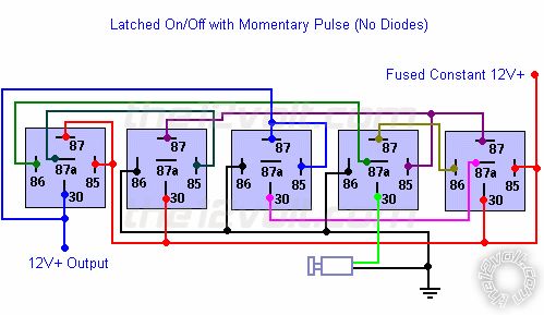
Is it possible to make a 12 volt circuit that uses bosch style relays and a single normally open pushbutton switch to latch and unlatch the circuit? I want the operation of this circuit to be as follows: push the pushbutton to latch the circuit and push the same pushbutton again to unlatch the circuit. The switch will control a ground and the output needs to be a ground. I would prefer NOT to use any diodes, transitors, or capicitors if possible, but if that's the only option so be it. I have tried the following diagram I got from this website and I think it works (for a 12 volt output), but when I push the button to unlatch the circuit, the small LED I used on the output wire just flickers. (I assume the circuit is unlatching and then relatching very very fast) Thanks in advance! Jason
Replies:
Posted By: awdeclipse
Date Posted: September 21, 2010 at 8:36 AM
Are you depressing the button manually and does it have to "reset" with a key cycle or anything?
5 relays seems like overkill to me for something that can be accomplished with a push button switch and a single relay to control the load.
Posted By: tbird311n
Date Posted: September 21, 2010 at 8:56 AM
Yes, I am pressing the button manually.
No, it doesn't have a "reset" that I am aware of?
If you use just a single relay and pushbutton, wouldn't you have to continuosly hold the button to maintain continuity in the circuit?
I guess what I am trying to accomplish is similar to another type of pushbutton switch that clicks when you push it. Once for on, and a second push for off. The only problem with that type switch is, I want the circuit opened as soon as I depress the button the second time, not when the pressure is released off the button.
Posted By: awdeclipse
Date Posted: September 21, 2010 at 9:37 AM
Yes I was suggesting a push button switch like you mentioned.
Posted By: oldspark
Date Posted: September 21, 2010 at 10:20 AM
Ditto, else a flip-flip circuit.
Yes - I know - that's electronics, but its easy with an inverter chip (hex inverter - enough for 2 switches!) else other gate chips, or transistors etc.
IMO that's much better than multiple relays, or a momentary to latching relay (for the mere price of $99), or circuitry with latching relays (unless zero "relay-ON" current is required).
Otherwise latching switches are a novel idea... (that's the ditto above).
Posted By: awdeclipse
Date Posted: September 21, 2010 at 10:30 AM
Flip-flop is a pretty good idea too with a simple set/reset. I haven't looked at those for years and I am not sure if they have enough current to drive a relay directly or if you need to amplify the output via a transistor.
Ugh the amount of stuff you forget when you use it so seldom.
Posted By: KPierson
Date Posted: September 21, 2010 at 12:10 PM
But the flip flop won't work by itself, you'll need a debounce circuit in front of it to provide stable, consistent results.
Then, you'll most likely need a transistorized output to control whatever you are trying to control. In the end you'll have a nice little prototype board with quite a few components on it.
I believe they make latching relays that can set and reset with the same inputs - that may be your easiest route. ------------- Kevin Pierson
Posted By: oldspark
Date Posted: September 21, 2010 at 4:43 PM
This is what I was thinking....
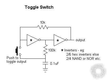
It's only 2 inverters - hence you could have 3 toggle switches per HEX inverter package, or 2 per quad NAND or NOR package (connect their inputs together to act as inverters). (A package being a 14-pin IC.)
I think it powers up in the OFF state.
An output buffer (transistor/FET) is probably required (but depending on what device is chosen and what load).
I'm sure transistors or FETs can be used instead of integrated inverters....
Posted By: awdeclipse
Date Posted: September 22, 2010 at 8:24 AM
TR7 Module
Check out option #3 this should do what you were looking for originally. They are not too expensive either for a universal solution.
Posted By: elanlover
Date Posted: September 24, 2010 at 8:43 AM
Wow. I've looked over this site for a few years now for ideas, info., etc., as I'm a real neophyte when it comes to this kind of thing. I'm working on a custom dash project and I'm integrating momentary push button fog light switches. So, I need a wiring plan to have this switch turn on and off the lights (through a relay of course) with a momentary signal. I just officially registered moments ago and lo and behold - the answer is here!
Is there any other way with simple relays to accomplish this? Great site!
|