switch with alarm accessory output
Printed From: the12volt.com
Forum Name: Relays
Forum Discription: Relay Diagrams, SPDT Relays, SPST Relays, DPDT Relays, Latching Relays, etc.
URL: https://www.the12volt.com/installbay/forum_posts.asp?tid=123687
Printed Date: May 09, 2026 at 2:43 AM
Topic: switch with alarm accessory output
Posted By: killerbean24
Subject: switch with alarm accessory output
Date Posted: September 27, 2010 at 5:40 PM
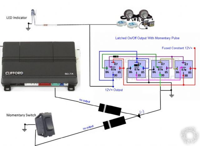
How do I wire a switch inside the cab to control the same output as one of my alarm accessory output wires?
Example: My HID off-road lights are hooked to an accessory wire from my alarm, which allows the HID's to be turned off and on via the alarm remote. How do I also wire them up so also be controlled via a switch inside the cab?
Replies:
Posted By: howie ll
Date Posted: September 28, 2010 at 1:10 AM
2 terminal switch, one side to ground other side to aux, BUT, at the aux, before you join wire off 2 diodes, 1N4004 in a Y shape, one to the HID relay, the other to your switch, bands towards the alarm/RS.
This will prevent a feedback possibly damaging your alarm.
-------------
Amateurs assume, don't test and have problems; pros test first. I am not a free install service.
Read the installation manual, do a search here or online for your vehicle wiring before posting.
Posted By: killerbean24
Date Posted: September 28, 2010 at 11:26 AM
So Like this?? Pin 30 doesn't look right to me.
Posted By: dualsport
Date Posted: October 03, 2010 at 9:17 PM
You show pin 30 permanently connected to ground, so your switches won't do anything. Just remove that connection to ground and it should be okay.
Posted By: killerbean24
Date Posted: October 04, 2010 at 12:58 PM
Pin 30 has to be either ground or power, right?
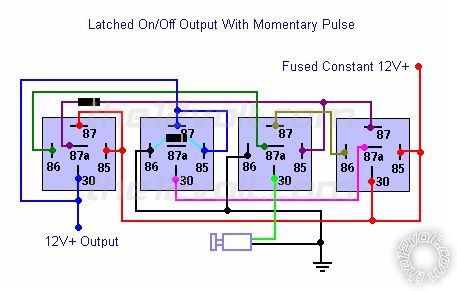
My diagram is based off this diagram on the relay's page...
 ------------- 2006 Dodge Ram 2500 * Superchips 3805 Tuner * Clarion NX500 * Kicker ZR600 * Kicker Solo-Baric 12 in custom center console
2003 BMW Z3 * Stock.. for now!!
Posted By: howie ll
Date Posted: October 04, 2010 at 1:35 PM
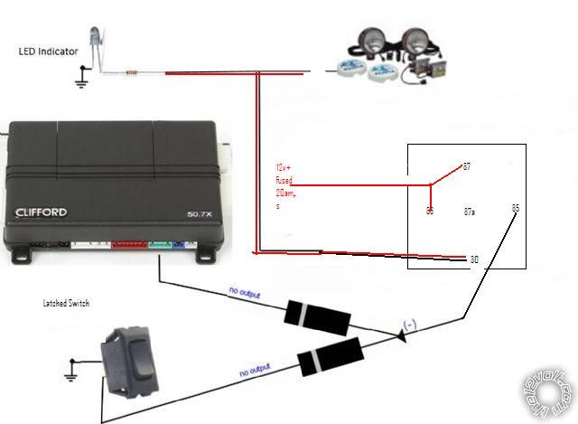
2A2_switch.jpg
This is all you need, if you use a latching circuit, how will you turn it off?
Alternatively leave the alarm's output as momentary, keep the momentary switch and feed a 528t or something similar, you7 can then set the time from 1 sec to 5 minutes. ------------- Amateurs assume, don't test and have problems; pros test first. I am not a free install service.
Read the installation manual, do a search here or online for your vehicle wiring before posting.
Posted By: killerbean24
Date Posted: October 04, 2010 at 2:03 PM
This doesn't work for my application, because once you send the negative pulse, the relay will only activate for a short period of time. I need the pulse to activate a latched circuit until another negative pulse is sent. My diagram is correct, except I can't figure out if pin 30 on the third relay is negative or positive. It appears to me that 30 needs to be a negative input to energize that relay. I guess I will just wire it up and test it real time.
-------------
2006 Dodge Ram 2500 * Superchips 3805 Tuner * Clarion NX500 * Kicker ZR600 * Kicker Solo-Baric 12 in custom center console
2003 BMW Z3 * Stock.. for now!!
Posted By: howie ll
Date Posted: October 04, 2010 at 2:16 PM
Forget all those relays and you can set the timing, use a 528t with a momentary switch. The 528t is wired as a normal relay, your latching circuit wont turn off.
30 SHOULD be the pos output from the relay to the lights. Basic amateur problem, you're over complicating things and getting in over your head.
-------------
Amateurs assume, don't test and have problems; pros test first. I am not a free install service.
Read the installation manual, do a search here or online for your vehicle wiring before posting.
Posted By: killerbean24
Date Posted: October 04, 2010 at 2:45 PM
Nevermind... Rookie mistake! I just wasn't attention to notice that 30 IS the negative trigger, and the others are just ground all the time. Woops. Here is the circuit...
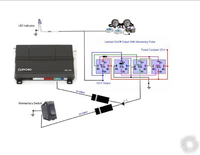
P.S. I am sure the 528t would do something similar, but for me, relays are much easier and cheaper to work with. $1.29/relay vs. $20 for the 528t. ------------- 2006 Dodge Ram 2500 * Superchips 3805 Tuner * Clarion NX500 * Kicker ZR600 * Kicker Solo-Baric 12 in custom center console
2003 BMW Z3 * Stock.. for now!!
Posted By: howie ll
Date Posted: October 04, 2010 at 4:18 PM
OK. That's a good price on those relays, I thought they were cheaper here, I pay equivalent to $1.20
-------------
Amateurs assume, don't test and have problems; pros test first. I am not a free install service.
Read the installation manual, do a search here or online for your vehicle wiring before posting.
Posted By: coolen
Date Posted: November 10, 2010 at 8:07 AM
Interesting thread, and seems very close to what I'm attempting to accomplish. I would like to be able to turn on/off my LED take down lights via remote off one of the - outputs on my remote start. It is currently wired through the "brain" of the lightbar. The lightbar is the ETL 5000 with break out box, and can be found here: https://soundoffsignal.com/warnamber/lightbars/lb_ETL5000.htm
When I installed it, I installed a switch in my console that is wired to the Take down light circuit and I can use those lights seperatly whenever needed. For example, if I don't want my reds flashing, I turn off the other functions of the bar via slide switch, and can use those lights by themselves (take downs). Very similar to the diagram above, just without the diodes on the relays themselves.
The way I was originally thinking was I'd need one relay to convert the - to +, then have another relay to power the lights. Then I THOUGHT I could just put a diode inline just after the relays. However according to some of the info I've been reading, it may not be that simple.
Any thoughts?
Thank you
|