capacitor value for latching relay?
Printed From: the12volt.com
Forum Name: Relays
Forum Discription: Relay Diagrams, SPDT Relays, SPST Relays, DPDT Relays, Latching Relays, etc.
URL: https://www.the12volt.com/installbay/forum_posts.asp?tid=124870
Printed Date: May 08, 2026 at 3:02 PM
Topic: capacitor value for latching relay?
Posted By: 98 SNAKE EATER
Subject: capacitor value for latching relay?
Date Posted: December 07, 2010 at 8:54 AM
In the past, I've always used a prebuilt latching relays from DEI whenever I needed one for an install, but since I have a ton of SPDT relays laying around, I figure I'd try making one for a change....
I'm basically looking to trigger a relay with a momentary pulse and have it remain latched until I turn the ignition off.
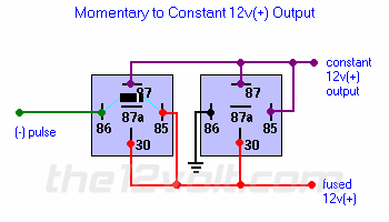
I figure this wiring diagram on page 5 is just what I need....
https://www.the12volt.com/relays/page5.asp#mtc
However, I'm a little lost when if comes to capacitor values....
In this case, what should it be?
Rick
Replies:
Posted By: i am an idiot
Date Posted: December 07, 2010 at 1:55 PM
There is no capacitor on that diagram. There is a Diode, which a 1N400X would be fine. X = any number from 1 to 7
Posted By: 98 SNAKE EATER
Date Posted: December 07, 2010 at 2:06 PM
i am an idiot wrote:
There is no capacitor on that diagram. There is a Diode, which a 1N400X would be fine. X = any number from 1 to 7
DOH!!!
I guess I can live up to your name lol
Not sure why I typed out cap??
Thanx for the info
Posted By: oldspark
Date Posted: December 07, 2010 at 7:23 PM
Nick off - I'm next in line for THAT name!
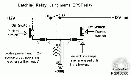
FYI - and it's not a good diagram (but it's public for now), but as a basis for a latching relay...
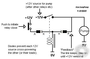
The diodes are only there to prevent cross connection via the switch(s).
The NC switch on the RHS "feedback" link isn't shown - ie, break this link by opening some contact to release the relay - or cut off its main/heavy +12V supply.
The +12V are shown separately to emphasis that they can be independent supplies. Often they are the same supply.
I use the same single SPST relay config for hi/lo water regulation; to latch car loads - often with a low-voltage switch (MW728 etc) in the "feedback" side (to unlatch with low battery voltage).
Posted By: 98 SNAKE EATER
Date Posted: December 08, 2010 at 12:43 PM
OK, after picking up a set of diodes, I wired up the relays and then realized it needs a negative pulse....
Is there a way I can wire it up to trigger on a positive pulse without using a 3rd relay?
Posted By: i am an idiot
Date Posted: December 08, 2010 at 1:57 PM
I see no way other than with a third relay.
Posted By: 98 SNAKE EATER
Date Posted: December 08, 2010 at 2:31 PM
i am an idiot wrote:
I see no way other than with a third relay.
<IMG alt="Momentary to Constant 12v+ Output Relay Diagram" src="https://www.the12volt.com/12voltimages/momentconstant.gif">
No problemo
I mocked up a couple of relays and it works fine with the negative pulse trigger, but I also tried it without the diode and it still works the same 
Posted By: oldspark
Date Posted: December 08, 2010 at 3:43 PM
You REMOVE a relay!
In that 2 relay (negative) Momentary to Constant Output diagram, the RHS relay is identical to my diagram except that the LHS relay is the NO switch.
[ Hence why is says " Or try connecting to a 12v(+) switched source instead of a constant one." - though I assume this isn't obvious? ]
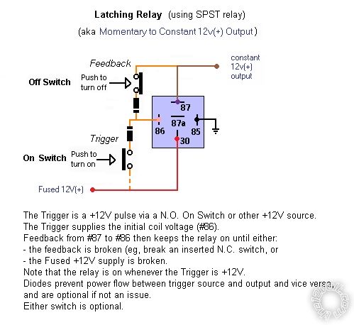
To convert to positive trigger as per my diagram (and using normal +ve to 86 convention), connect #85 to ground, #87 via diode to #86, and the +12V input via a diode also to #86.
If the trigger can power the load, the diodes can be omitted - ie, connect the output #87 and the trigger to #86.
The trigger might be a switch from the fused +12V (#30).
If this isn't clear, I can get a better diagram to my earlier.
I can also draw a (corrected) version of Momentary to Constant Output for +12V trigger.
The diode shown in Momentary to Constant Output is not required per se - it is only for spike suppression (from the LHS relay).
Strictly speaking, both coils are shown with inverted polarity - terminals 65 & 86 should be swapped in case internal-diode relays are used (though I recommend external diodes as shown on the LHS relay in Momentary to Constant Output).
The is an example of why I dislike the physical diagrams like Momentary to Constant Output - IMO it is too difficult to see or understand what is happening.
You may be used to them, but I prefer (or need?) the functional diagrams. (I can then merely assign the numbers - even though in practice I use the schematic supplied on the relay - though I do know which are the (un-polarised) coil and the heavy contacts. The actual numbers tend to be irrelevant.)
Posted By: oldspark
Date Posted: December 09, 2010 at 8:26 AM
I couldn't resist....
For you:
For me:
Posted By: i am an idiot
Date Posted: December 09, 2010 at 8:40 AM
The top switch of the top diagram is not needed. If you use an ignition feed for the wire labeled Fused 12v, it will work just as you desire. You do need the diodes, but not the top switch.
Posted By: 98 SNAKE EATER
Date Posted: December 09, 2010 at 8:44 AM
Thanks for taking the time to make the diagram 
I was actually going to try it out later today....
That being said, I'll most likely end up going with 3 relays and no diodes since I have a ton of them with pigtails that snap together for a clean install....

Posted By: oldspark
Date Posted: December 09, 2010 at 9:24 AM
I forgot to say that the top switch (feedback, or the actual latch "hold" signal) can also be a low voltage cutout - eg, an MW728 battery protector.
Hence if you forget to turn the load off, the battery won't drain too far.
I usually draw both switches because (IMO) it's easier to imagine omitting them as opposed to inserting. Hence the "either is optional" (Others can draw both or all 3 versions if needed.)
Besides, that diagram is the original "sump pump" circuit - ie, pump on to empty when above the upper level.
Merely invert the switch assembly to fill a tank when it's below a certain level.
It's often used for alarms, or PCs with the trigger switch ommited (ie, shorted out) so the PC comes on with IGN or ACC, but stays on when the IGN/ACC is turned off until OFF is pressed (or an MW728 etc breaks the feedback).
A timer can be added in parallel to the ON switch for a delayed turn on.
|