converting polarity issue
Printed From: the12volt.com
Forum Name: Relays
Forum Discription: Relay Diagrams, SPDT Relays, SPST Relays, DPDT Relays, Latching Relays, etc.
URL: https://www.the12volt.com/installbay/forum_posts.asp?tid=125432
Printed Date: May 09, 2026 at 6:45 AM
Topic: converting polarity issue
Posted By: scam404
Subject: converting polarity issue
Date Posted: January 03, 2011 at 5:23 PM
I am having a weird issue when doing a simple polarity conversion for use with a positive door trigger input. I have a Viper 5901 installed on my 09 Mazdaspeed 3. The factory door triggers show ground when the doors are closed and go to an open circuit when a door is open. I have the door triggers diode isolated and hooked up to the positive trigger input of the brain using a +12V source and resistor method.
This is my issue, i have a 516L voice module hooked up to my alarm as well, and everything is connected and works properly except for the door trigger input to the voice module. The 516L only has a negative door trigger input, so I hooked up my relay to convert the polarity from pos to neg so I could hook up this input for my voice module (its only real purpose is for the module to announce "check doors" if you forget to close a door). I followed the diagram in the 516L manual as well as the diagram on this forum for converting polarity using a relay, and I tried two different relays, but still had the same issue. I connected the positive door trigger wire to 85, ground to 86 and 30, and the negative door trigger input to the voice module to 87.
The problem is when I hook up the relay with all four wires, something strange happens with the door triggers, and even if I have a door open the little light on the gauge cluster that indicates a door is open goes out. This seems like a need a diode somewhere, but I do not know where. I appreciate any help you guys can provide.
Replies:
Posted By: oldspark
Date Posted: January 03, 2011 at 6:20 PM
Without knowing the vehicle or Viper etc specifics, but based on your description....
It sounds to me like you do NOT need inversion.
IE - a +ve trigger means from GND to +ve when triggered.
I presume the trigger is the door(s) opening.
And if the doors (switches) are GND when closed, then they go +ve when opened. That assumes a pull-up device - like a resistor or bulb etc.
Note that often door switches are open (floating) when closed and closed when open. (Get that - open when closed and close when open - simple!)
EG - a single-wire door switch is GND when the door is open and is floating when the door is closed (which opens the door switch).
That's a traditional door switch that GNDs dome lights etc. (ie, hot dome lights that are +12V on one side, and the door switch or manual switch grounds the other side to light it.)
With that traditional wiring, the door switch is +12V when closed (because the dome light pulls it to +12V) and is GND when open - ie, it is a NEGATIVE going transition from +12V to 0V/GND when opening the door.
But yes - your problem is probably a diodic one. (If diodic isn't a valid word, it is now.)
It is usually a simple case of using two diodes, but in the right places AND directions.
And often ticky to work out yet oh-so-simple when seeing it in a simple diagram. (I know - after decades of intent, recently I FINALLY fitted a headlight reminder to my vehicle - only 10 years & $1.50 - the 10 years because my latest vehicle found me in 1999-2000.)
But first, can you confirm your door switch is as you describe. ie - it is not a single-wire grounded when door-is-open, but is closed (grounded) when the door is closed, else maybe a 2-wire switch that opens/closes +12V?
Posted By: scam404
Date Posted: January 03, 2011 at 8:08 PM
oldspark wrote:
Without knowing the vehicle or Viper etc specifics, but based on your description....
It sounds to me like you do NOT need inversion.
IE - a +ve trigger means from GND to +ve when triggered.
I presume the trigger is the door(s) opening.
And if the doors (switches) are GND when closed, then they go +ve when opened. That assumes a pull-up device - like a resistor or bulb etc.
Note that often door switches are open (floating) when closed and closed when open. (Get that - open when closed and close when open - simple!)
EG - a single-wire door switch is GND when the door is open and is floating when the door is closed (which opens the door switch).
That's a traditional door switch that GNDs dome lights etc. (ie, hot dome lights that are +12V on one side, and the door switch or manual switch grounds the other side to light it.)
With that traditional wiring, the door switch is +12V when closed (because the dome light pulls it to +12V) and is GND when open - ie, it is a NEGATIVE going transition from +12V to 0V/GND when opening the door.
But yes - your problem is probably a diodic one. (If diodic isn't a valid word, it is now.)
It is usually a simple case of using two diodes, but in the right places AND directions.
And often ticky to work out yet oh-so-simple when seeing it in a simple diagram. (I know - after decades of intent, recently I FINALLY fitted a headlight reminder to my vehicle - only 10 years & $1.50 - the 10 years because my latest vehicle found me in 1999-2000.)
But first, can you confirm your door switch is as you describe. ie - it is not a single-wire grounded when door-is-open, but is closed (grounded) when the door is closed, else maybe a 2-wire switch that opens/closes +12V?
oldspark, thank you for your reply, but I am not sure if you just did not read my post, or you just missed the make and model of my car, as well as the model of alarm, but that information was in the first line of my post. Yes, I am sure that my door triggers are as I described, I installed the remote start and alarm myself and they are quite non traditional triggers.
Posted By: oldspark
Date Posted: January 03, 2011 at 9:32 PM
No - I did not miss that info.
Sorry for my vagueness - I simple meant that although I know what they are, I have no idea about the specifics involved - ie, I cannot confirm that the 09 Mazda is grounded-closed doors. (I do know 1990 323s and earlier are not.)
It'll take a while for me to post a pic though....
(Maybe you have a simple "line" diagram or reference I could use or check?)
Posted By: KPierson
Date Posted: January 03, 2011 at 10:43 PM
So you have 12vdc going through a resistor to a relay? That won't work as the resistor will limit the current most likely to the point that the relay won't have enough current to pull in. What is the size of the resistor?
This would be a much better application for a reed relay or a transistor.
-------------
Kevin Pierson
Posted By: scam404
Date Posted: January 03, 2011 at 10:54 PM
KPierson wrote:
So you have 12vdc going through a resistor to a relay? That won't work as the resistor will limit the current most likely to the point that the relay won't have enough current to pull in. What is the size of the resistor?
This would be a much better application for a reed relay or a transistor.
I was thinking the same thing, after talking another guy who is an installer I am going to try using the dome light positive wire to trigger the relay.
Posted By: howie ll
Date Posted: January 04, 2011 at 8:52 AM
Forget about inverting, like Fords,(it's a Focus)the door pins go to OPEN CIRCUIT on that vehicle, two answers:
On some Viper's, I know you can with the 5902, change the door pin configuration to open circuit via the programming.
Or use the following DEI part for it. DTIMazda.
-------------
Amateurs assume, don't test and have problems; pros test first. I am not a free install service.
Read the installation manual, do a search here or online for your vehicle wiring before posting.
Posted By: scam404
Date Posted: January 04, 2011 at 9:05 AM
Thanks Howie, but the issue isn't with the door trigger to the alarm. I am just trying to switch over the positive door trigger to a negative signal to be connected to my voice module (because it only accepts a negative input), so it can say "check doors" if I leave a door open. Kind of pointless really, but I just like using all the available features when I install stuff.
Posted By: howie ll
Date Posted: January 04, 2011 at 9:13 AM
Except it isn't positive! It's neg when the doors are closed and OPEN CIRCUIT when the doors a opened.
Use the DTIMazda to get your neg signal.
-------------
Amateurs assume, don't test and have problems; pros test first. I am not a free install service.
Read the installation manual, do a search here or online for your vehicle wiring before posting.
Posted By: scam404
Date Posted: January 04, 2011 at 9:31 AM
howie ll wrote:
Except it isn't positive! It's neg when the doors are closed and OPEN CIRCUIT when the doors a opened.
Use the DTIMazda to get your neg signal.
I know that the triggers rest at ground when closed and Open circuit when open, I have already taken care of the door triggers by running a fused 12V source that splits off into four different branches (one for each trigger), each branch has a 10K resistor wired in. Then I have each of the triggers diode isolated and all four are connected to the single positive door trigger input for the alarm.
That is what is causing the whole issue, when I try to hook up the relay using the lead from the positive input, it is allowing the positive signal to go to ground and the car thinks that no doors are open. I am going to attempt using the positive wire from the dome light to trigger the negative input instead, if that fails then I will just say screw it and go without this feature.
Posted By: KPierson
Date Posted: January 04, 2011 at 11:09 AM
 ------------- Kevin Pierson
Posted By: scam404
Date Posted: January 04, 2011 at 11:59 AM
Kevin,
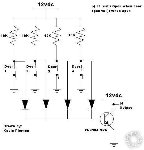
Thanks a lot for that diagram. I have never used a transistor before, but I have been reading about them and they do not seem to be too difficult. I imagine in this case I will not be amplifying any signal but instead just using the transistor as a switch. On your diagram at the bottom you show the output as a negative out, but you have it labeled as 12 VDC, are you just saying that it is a ground output? Also, on my install I diode isolated all four of the door triggers, but I do not see any diodes on your diagram, that will not make a difference will it?
Posted By: KPierson
Date Posted: January 04, 2011 at 12:53 PM
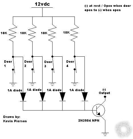
The diodes are there - they are the black triangles before all four switches come together.
The transistor collector should NOT be connected to 12vdc. I'm not sure why I did that. That (-) output should be connected directly to the (-) input of the alarm and voice module.
Make sure you connect the emitter of the transistor to ground, the base to the output of all 4 doors, and the collector to the inputs of the devices. Should be pretty easy. ------------- Kevin Pierson
Posted By: howie ll
Date Posted: January 04, 2011 at 12:53 PM
Scam, the diodes are represented by the arrows at bottom going to the transistor.
The bands would be towards the transistor.
I agree with your polarity comment, what's the answer KP?
-------------
Amateurs assume, don't test and have problems; pros test first. I am not a free install service.
Read the installation manual, do a search here or online for your vehicle wiring before posting.
Posted By: howie ll
Date Posted: January 04, 2011 at 12:55 PM
Sorry, KP, bad timing.
-------------
Amateurs assume, don't test and have problems; pros test first. I am not a free install service.
Read the installation manual, do a search here or online for your vehicle wiring before posting.
Posted By: scam404
Date Posted: January 04, 2011 at 12:58 PM
thanks a lot guys, this forum is awesome. I am actually getting to use some of the crap I am learning about in my electrical engineering classes.
Posted By: oldspark
Date Posted: January 04, 2011 at 3:01 PM
I presume the output's input has a pull-up resistor etc? (IE - In KP's tranny diagram. That's a classic "open collector" output - great stuff - the "universal interface solution".)
I also note a lack of base resistor... Base current will vary 4-fold depending on how many switches are open.... OH NO IT WON'T! Geez there are some idiots on this forum! Base current will be via 2.5k else nothing. (~12V/2k5 ~5mA)
See - I knew KP was right!
... Though I was going to suggest a FET to overcome that - ie, "base" = gate current irrelevant (nA or uA), merely its gate voltage higher than about 5V to turn on, but must be pulled low for off (normally a resistor as with a transistor, but 1M etc - but not needed in this case because either a switch pulls it to ground else dosn't.
Of course one wonders how those diodes will pull the base or gate down to 0V/GND with that orientation - but maybe I am the "one" that wonders that?
I'd have them the other way with a single base/gate resistor to +12V (eg, 2.5k => 2.2k or 2.7k etc, or 1M (or 1k to 10M) for the FET)....
But it is before 8AM here.... (and I skipped the switch resistance detail).
And of course, only "the first" door triggers, and last door "resets" - ie, the change occurs between all closed and [any or all] open.
Coffee time.... Then maybe a second laugh at some nameless dork, else maybe a chance to redeem mys... him/herself. (I'll bet the former...)
(More) Trivial FYI only:
scam404 wrote:
I am actually getting to use some of the crap I am learning about in my electrical engineering classes.
WHAT?
It wasn't until 3rd year that happened to me - and that was merely finding out that by moving the fast brush closer to the ground brush in my wiper motor, I would have a reasonable high speed instead of "slow plus stuff all".
Mind you - I was totally rapt. It took 3 years, but I finally learned something practical.
Compare that to second year where I had a lecturer removed when he suggested the LM317 adjustable 3 terminal voltage regulator was "probably" adjusted with a screw driver.... and that was for a practical "Design" class lab-prac! (Actually I let that one go. I had him removed later when - in his other "theoretical" Electronics class - he scoffed at those that couldn't "design" as simple 2 stage tranny amp (but with DC coupling!). Yet neither could he as we later confirmed. That was an other implementation of what some knew or now know as "DFWAA". I won't mention the other times, but I strongly suggest you "go with the masses" - never EVER correct long erred beliefs or prac class results - let others do that. But it was good training for real life LOL!)
Sorry - I love formal education and qualifications as you may well be aware. (Experience - just get that from a book or school. My old uni still uses the latest in SSL2 protocols and new yet disparit(??) IT systems with manual transfers - of REPEAT info! But my later uni now allows working in groups and does not consider it "cheating"! Masters of F-wits those Degrees!)
Posted By: KPierson
Date Posted: January 04, 2011 at 3:17 PM
I run much higher resistances through a diode though the base of a 3904 with no issues (as high as 1.5 megaohm). Because the transistor is only a switch the changing of the base resistance won't matter.
The alarm inputs should have pull ups on them as most car alarms are NO and go to ground when door is closed. This, is theory, of course, and a 10K resistor can be placed between the (-) output and 12vdc if there are any issues. ------------- Kevin Pierson
Posted By: scam404
Date Posted: January 04, 2011 at 4:00 PM
Ok I just got done installing the transistor, and everything works perfectly now. That thing was a real pain to solder to the individual wires though. Is there some way I dont know about to solder those things? It looks like it is meant for circuit board use only... I had to CAREFULLY put tiny pieces of electrical tape on each one to keep them from touching.
Posted By: KPierson
Date Posted: January 04, 2011 at 4:06 PM
I would have bought a little prototype board and soldered it ot that, then soldered the wires to the bottom of the board. If you solder directly to the pins and make sure all the wires are taped together so no individual leg can be pulled off you'll be ok. Alternatively, you could have went with a much larger NPN transistor that is available in a TO220 package - a little friendlier then the TO92 package.
-------------
Kevin Pierson
Posted By: KPierson
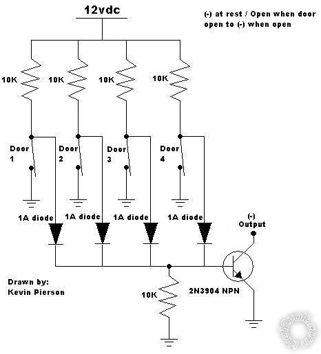
Date Posted: January 04, 2011 at 4:09 PM
Here is an updated, accurate drawing - sorry for the mistakes earlier.
------------- Kevin Pierson
Posted By: scam404
Date Posted: January 04, 2011 at 4:31 PM
KPierson wrote:
I would have bought a little prototype board and soldered it ot that, then soldered the wires to the bottom of the board. If you solder directly to the pins and make sure all the wires are taped together so no individual leg can be pulled off you'll be ok. Alternatively, you could have went with a much larger NPN transistor that is available in a TO220 package - a little friendlier then the TO92 package.
I think I will go back and use a bigger one because I don't want that smaller one breaking on me over time. Can I just buy any NPN that is in a TO220 case? Also, should I use a proto board on the 220 as well?
Posted By: KPierson
Date Posted: January 04, 2011 at 6:05 PM
I would think on the TO220 you could solder directly to the pins. On the TO92 as long as you secure all three wires and did a decent job soldering you shouldn't have any issues.
-------------
Kevin Pierson
Posted By: tonanzith
Date Posted: January 04, 2011 at 6:32 PM
Your relay is wired wrong.
85 should be the positive door trigger
86 and 87 should be ground
30 should go to the - trigger input of the module
87a should have nothing.
NO DIODES needed. The relay replaces diodes.
-------------
Gary Sather
Posted By: KPierson
Date Posted: January 04, 2011 at 6:37 PM
tonanzith wrote:
Your relay is wired wrong.
85 should be the positive door trigger
86 and 87 should be ground
30 should go to the - trigger input of the module
87a should have nothing.
NO DIODES needed. The relay replaces diodes.
There is no electrical difference between the way he had it wired and the way you say to wire it. Simply swapping Pins 30 and 87 will not change anything. The problem is that his + door pin voltage is going through a 10Kohm resistor which will limit his current to around 12mA - not nearly enough to pull a relay coil in. ------------- Kevin Pierson
Posted By: tonanzith
Date Posted: January 04, 2011 at 6:39 PM
Scratch that I read the post wrong. just use the dome light wire. it is - color is BLACK/ light blue and is found passenger kick or PJB, 46 pin plug (J-05), pin U The PJB (Passenger Junction Box) is behind the glove box. it is a straight - when any door is open and nothing when doors are closed and will work perfectly for the module.
-------------
Gary Sather
Posted By: scam404
Date Posted: January 04, 2011 at 11:45 PM
OK, well i thought everything was running correctly... but i was wrong. The door trigger is functioning correctly using the transistor. The alarm still goes off if I arm the alarm, and then reach in the window and open the door, and the voice module announces "check doors" if i leave a door open and arm the alarm. However, something else weird is now happening with the dome light/door trigger. When I remote start the car, it starts correctly, but then immediately says "intruder alert, door access" so it must be getting a ground at the door trigger input when the car starts. The issue is also affecting the dome light when the car is running on remote start, the dome light will not come on like it did before I installed the transistor.
Posted By: KPierson
Date Posted: January 05, 2011 at 7:09 AM
So are you ONLY using the (-) door trigger now?
Do you have anything hooked up from the dome light output to make the dome light turn on when you remote start?
You may want to try diode isolation the two (-) door pin inputs just to make sure they are not backfeeding.
Something else you may want to try is to add a resistor from the base of the transistor to ground. This will make sure it stays off when there is no signal present.
 ------------- Kevin Pierson
Posted By: scam404
Date Posted: January 05, 2011 at 8:04 AM
Kevin,
Yes I am only using the negative door trigger now, I have it split off into two branches when it leaves the collector and going into the (-) door trigger inputs of the alarm and the voice module. Would it help if I hooked the positive input to the brain back up? And then used the (-) output from the collector to trigger the voice module? If that will not help and you think I should just install the diodes and resistors, I need to have the cathode side facing the transistor in each of the two branches right?
Posted By: scam404
Date Posted: January 05, 2011 at 12:13 PM
Well heres an update, during my lunch break i wired in two diodes, one for each door trigger input, and hooked up the resistor between the base and ground. This fixed the dome light issue, but it did not fix the issue with the triggers. Whenever i remote started the car, and open and shut a door, the voice module would say "intruder alert, door access" so somehow the door trigger was still getting a ground.
So then I disconnected the negative door trigger input going to the alarm, and reconnected the positive input. Well this caused the door triggers to not work again, and somehow still made the voice module say intruder alert whenever i closed a door after remote starting. Needless to say i was pretty discouraged at this point, so i disconnected the transistor completely and I am going to try just using the negative wire from the domelight as a negative input to the voice module when i get home. If that does not work then who knows...
Posted By: KPierson
Date Posted: January 05, 2011 at 1:27 PM
So are you saying when the car is remote started AND you OPEN the door the voice module tells you the door is open? Is the alarm armed or disarmed at that point? What tells the voice module that the alarm is armed? It seems to me that the door pin portion is working but something else is not connected right. ------------- Kevin Pierson
Posted By: howie ll
Date Posted: January 05, 2011 at 1:32 PM
Yes shouldn't the voice module be controlled via the alarm's GWA wire?
-------------
Amateurs assume, don't test and have problems; pros test first. I am not a free install service.
Read the installation manual, do a search here or online for your vehicle wiring before posting.
Posted By: KPierson
Date Posted: January 05, 2011 at 2:19 PM
Thats what I would think
-------------
Kevin Pierson
Posted By: scam404
Date Posted: January 05, 2011 at 2:23 PM
KPierson wrote:
So are you saying when the car is remote started AND you OPEN the door the voice module tells you the door is open? Is the alarm armed or disarmed at that point? What tells the voice module that the alarm is armed? It seems to me that the door pin portion is working but something else is not connected right.
OK, here is how i have everything set up. I have the 5901, then i have a PKFM security bypass installed, I have a 516L voice module, and a 507M tilt sensor.
The voice module has inputs for the GWA from the alarm, (-) door trigger, and the + siren wire from the alarm. I have the GWA and the siren wire hooked up, and I had the negative door trigger input connected like in kevin's diagram. The weird thing is this, i checked the manual for the 516L and the message "intruder alert, door access" is only supposed to be announced when the system is armed.
I am thinking it might be an issue with the way i have my GWA wires hooked up. The tilt sensor and voice module are both connected to this wire and they are not diode isolated from each other. I am not sure if that matters or not though. In order for the voice module to be announcing the intruder alert message it has to think the alarm is armed even though it is not... which is weird.
Posted By: scam404
Date Posted: January 05, 2011 at 2:27 PM
and to answer your other question about the voice module, it was telling me intruder alert only when i SHUT the door, not while it was open
Posted By: KPierson
Date Posted: January 05, 2011 at 2:52 PM
All devices on the GWA wire need to be diode isolated. I'm not 100% sure that will fix the problem, but that is, without a doubt, where I would start first.
-------------
Kevin Pierson
Posted By: scam404
Date Posted: January 05, 2011 at 7:46 PM
OK... well this will be my last post on this topic as I am giving up on it now. I went back and diode isolated the GWA wires, and hooked up the negative wire from the dome light to the voice module's (-) door trigger input. This worked perfectly for getting the voice module to do what i wanted it to do, which was say "check doors" when i left a door open and armed the alarm. However, when I remote started the car and got in, and then shut the door, the stupid thing was still saying, "intruder alert" so i said screw it and just unhooked the door trigger input to the voice module. I am convinced that something has gone wrong inside the voice module itself, because it is only screwing up while the car is running on remote start that must be the case. The door trigger input works perfectly when the car is off. Anyhow, thank you for all your help on this one guys, I will now be moving on to my next challenge, installing two 530t window modules, which should prove to be fun.
Posted By: KPierson
Date Posted: January 05, 2011 at 8:16 PM
I refuse to let that be your last post about this!
I'm still convinced something simple is wired wrong. How does the voice module "know" that the car is remote started?
By changing the door pin wire to the dome light you now know the issue isn't with that signal, so there has to be something else.
Is it possible that your gwa wire is also a gwr wire? I think I remember somewhere that certain alarms do that. Have you checked the gwa wire with a meter to see what is going on? Worst case scenario install a relay controlled by the status output of the alarm that breaks the gwa signal going to the voice module. Don't give up!
-------------
Kevin Pierson
Posted By: scam404
Date Posted: January 05, 2011 at 9:11 PM
Kevin,
The voice module also has two inputs for the remote start, one is connected to the remote start's accessory output, and the other is connected to the status output of the remote start. The module is functioning correctly when the car remote starts, it says, "valet now starting engine, stand clear" then once the car starts it says "caution, valet operating vehicle". So i know the module is working correctly in that aspect. I am pretty sure the wire is a GWA only, but i can double check that. I would like to figure this out, just because i have spent so much damn time on it.
Posted By: tonanzith
Date Posted: January 06, 2011 at 12:44 AM
Those two wires are both NEGATIVE inputs on that module. One goes to the - status output from the remote start and the accessory input wire which should be ORANGE / black should go to the orange wire from the remote starts auxiliary harness. This is NOT the thicker orange ground when armed wire from the main harness but the thinner orange one in the 5 pin auxiliary harness that also has a pink/white, violet, pink and blue wire in the harness.
-------------
Gary Sather
Posted By: scam404
Date Posted: January 06, 2011 at 9:19 AM
tonanzith wrote:
Those two wires are both NEGATIVE inputs on that module. One goes to the - status output from the remote start and the accessory input wire which should be ORANGE / black should go to the orange wire from the remote starts auxiliary harness. This is NOT the thicker orange ground when armed wire from the main harness but the thinner orange one in the 5 pin auxiliary harness that also has a pink/white, violet, pink and blue wire in the harness.
yes i know that, that is how i have them connected and that is why the remote start announcements are working correctly.
Posted By: scam404
Date Posted: January 11, 2011 at 6:37 PM
OK for anyone who might care, i think i finally figured out what was going on with my voice module acting up. I was looking through my viper install manual at some of the options that you can program, and this is one of the options : 3-13 Anti-Grind: On (1) OFF (2): With the anti-grind On (default) the ground when-armed output is active during remote start operation. This activates the starter kill relay and prevents the customer from re-cranking the car with the key, when doing key takeover. If accessories such as a voice module or window module are added to the unit, it may be necessary to use the two-chirp setting to program this feature OFF.
SO, this means that the GWA wire was putting out a ground while the remote start was activated, and that made the voice module think that the car was still armed. This is why the voice module worked correctly when the car was off and was acting weird while it was running via remote start.
Posted By: KPierson
Date Posted: January 11, 2011 at 7:33 PM
Haha, I believe someone might have mentioned something about that in this thread!
Good to know I'm not crazy and that you figured it out!
-------------
Kevin Pierson
Posted By: scam404
Date Posted: January 11, 2011 at 11:13 PM
yea thats what got me thinking to look at the manual and make sure, thanks KP, hey i tried sending you a pm but your inbox was full, that was a week or so ago, is it still full?
Posted By: KPierson
Date Posted: January 12, 2011 at 1:36 AM
It's cleaned out now, sorry about that!
-------------
Kevin Pierson
|