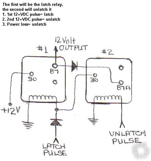
latched on/off output, 2 momentary inputs
Printed From: the12volt.com
Forum Name: Relays
Forum Discription: Relay Diagrams, SPDT Relays, SPST Relays, DPDT Relays, Latching Relays, etc.
URL: https://www.the12volt.com/installbay/forum_posts.asp?tid=126920
Printed Date: April 12, 2026 at 11:45 AM
Topic: latched on/off output, 2 momentary inputs
Posted By: woodsbuggy3
Subject: latched on/off output, 2 momentary inputs
Date Posted: April 11, 2011 at 10:39 AM
I want to use the circuit below but I need both pulsed triggers to be + instead of - , how would I go about doing that?
Replies:
Posted By: howie ll
Date Posted: April 11, 2011 at 11:11 AM
Make the red wire in the diagram go to ground.
-------------
Amateurs assume, don't test and have problems; pros test first. I am not a free install service.
Read the installation manual, do a search here or online for your vehicle wiring before posting.
Posted By: woodsbuggy3
Date Posted: April 11, 2011 at 11:22 AM
Then what do I do with 85 on the center relay? just wire it to + ?
I guess I was afraid that would break the latching function?
Posted By: howie ll
Date Posted: April 11, 2011 at 12:25 PM
If you want a negative output leave it as it is, if you want a positive output, make the black in the diagram positive. This isn't rocket science.
-------------
Amateurs assume, don't test and have problems; pros test first. I am not a free install service.
Read the installation manual, do a search here or online for your vehicle wiring before posting.
Posted By: woodsbuggy3
Date Posted: April 11, 2011 at 12:35 PM
I know, its just been a long time since I have done this stuff! I appreciate your help.
So this is what I want then, right?

Posted By: hotwaterwizard
Date Posted: April 13, 2011 at 12:34 AM
 ------------- John DeRosa (Hotwaterwizard)
Stockton California
When in doubt, try it out !
Posted By: the12volt
Date Posted: April 13, 2011 at 12:53 AM
woodsbuggy3 wrote:
I want to use the circuit below but I need both pulsed triggers to be + instead of - , how would I go about doing that?
Connect the terminals in the diagram that go to the negative pulses to turn on and off to ground (terminal 86 of the first relay and terminal 85 of the third relay). Terminal 85 of the first relay and terminal 86 of the third relay will no longer go to a constant 12V+ source. Instead, terminal 85 of the first relay will be your positive input to turn on and terminal 86 of the third relay will be your positive input to turn off. When i get a moment, I'll draw one to add to the database. -------------  the12volt Support the12volt.com the12volt Support the12volt.com
Posted By: the12volt
Date Posted: April 13, 2011 at 10:54 PM
Posted By: howie ll
Date Posted: April 14, 2011 at 1:36 AM
Er guys were running around in circles here, 12volt and HWW you're both correct but this is what I told the poster to do originally!
-------------
Amateurs assume, don't test and have problems; pros test first. I am not a free install service.
Read the installation manual, do a search here or online for your vehicle wiring before posting.
Posted By: the12volt
Date Posted: April 14, 2011 at 1:42 AM
Howie, read what the op wrote and your replies again. He was asking for positive input pulses. Making the red wire go to ground is not the solution. See the diagram I linked to in my previous post. https://www.the12volt.com/relays/relaydiagram63.html------------- the12volt Support the12volt.com
Posted By: howie ll
Date Posted: April 14, 2011 at 1:46 AM
Point taken, had I read it properly I would have pointed out how simple this is. I wish people would read the BRILLIANT intros to relays and diodes here.
-------------
Amateurs assume, don't test and have problems; pros test first. I am not a free install service.
Read the installation manual, do a search here or online for your vehicle wiring before posting.
|