relay for electric fan
Printed From: the12volt.com
Forum Name: Relays
Forum Discription: Relay Diagrams, SPDT Relays, SPST Relays, DPDT Relays, Latching Relays, etc.
URL: https://www.the12volt.com/installbay/forum_posts.asp?tid=127120
Printed Date: April 12, 2026 at 2:41 AM
Topic: relay for electric fan
Posted By: IKESSKY
Subject: relay for electric fan
Date Posted: April 26, 2011 at 12:50 PM
I'm hoping the gurus here can help me with a little question I have about installing an electric fan in my truck. This is the diagram I will be using: https://img.photobucket.com/albums/v697/ikessky/schematic.gif
This is the relay that is supposed to be used in the diagram: https://img.photobucket.com/albums/v697/ikessky/relay_0332002156_relay_drawing.gif
Here is a relay that I can get for free: https://img.photobucket.com/albums/v697/ikessky/relay_0332002150_relay_drawing.gif
I see that the difference in relays is that the 156 has an internal diode. What am I at risk of if I use the 150 relay instead? From what I can tell, I could risk back-feeding a voltage spike into my fan controller if I don't have the diode.
Replies:
Posted By: oldspark
Date Posted: April 26, 2011 at 5:39 PM
You are "at risk", but fairy small.
But you can easily add an external diode - typically a 1N400x type (1N4004, 1N4007). Cost about 5c to 20c each - though I suggest by several - even a pack of 10 or 100 (100 for $5).
They come in handy when (a) you lose or wreck the first "one & only" you bought with $15 P&P or petrol, & (2) whenever you want to parallel or interconnect different signals to control a relay or lamp etc, or suppress other spikes etc.
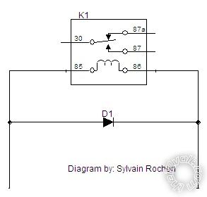
The diode "line" end should go towards the +ve end of the coil (ie, #86), other end to -ve end (ie, #85).
Posted By: syl20rochon
Date Posted: April 26, 2011 at 6:09 PM
Make sure the your relay is rated at 75amps and yes use external diodes to avoid spikes.
-------------
Sylvain Rochon
MECP security specialist
Tech support for remote starters
26 Years of experience counts
I'm here to help.
Posted By: IKESSKY
Date Posted: April 26, 2011 at 8:34 PM
I'm sure that I can find some diodes at work that I can use also. The relay I will use is a 75a, it just doesn't have the internal diodes like the one in the original diagram. I'm already putting a 1N5406 diode (600V, 3.0A) on the fan itself. Would one of those work on the relay also or is that too big? I see the ones you recommended are only 1.0A.
When I wire in the diode, does it matter how I do it or just that it connects from the wires on #85 and #86 (like an "A" or a "H" if you will)? Obviously which end goes where matters, as you stated before.
Posted By: syl20rochon
Date Posted: April 26, 2011 at 8:49 PM
A diode is like a fuse, the coil of a relay draws around 150mA so I would recommend a 1amp diode. Also, make sure that you install it in it's proper polarity. The grey lines is called a cathode and should be on the positive side.
 ------------- Sylvain Rochon
MECP security specialist
Tech support for remote starters
26 Years of experience counts
I'm here to help.
Posted By: IKESSKY
Date Posted: April 26, 2011 at 9:47 PM
That answers my questions perfectly! I greatly appreciate all the help guys! This truly is a low buck project. I bought the controller on ebay for less than $20, the relay and diodes are free, and the fan will run me around $60 or less!
Posted By: oldspark
Date Posted: April 27, 2011 at 2:52 AM
With thanks to syl20rochon - at last! - my style of diagram.
And I'll probably use that in the future (assuming that is ok) though I might add a + & - to show the major point that the Kathode (line) end goes towards +ve. [Otherwise the diode is forward biased hence effectively a short between + & - and hence blowing the control circuit or fuse or the diode!]
IMO it's a great diagram. It even "aligns" the main contacts to show that 87a is "normally" connected (hence its NC label/designation where Normally means as if it's on the shelf - ie, de-energised - as opposed to whatever its normal operating position might be...
And it shows that the switch arm goes to the NO Normally Open #87 contact when the coil is energised thereby pulling the arm in towards the coil.
Those conventions seem to be common and what I endeavor to do in circuit diagrams, though for layout reasons that may not always be followed (ie, Reader: always beware!). But I always show relays in their de-energised state (ie, "Normal") EXCEPT when explaining how a circuit works whereby I might show it in its energised/closed position to clarify power flow...
The actual relay-coil ends are really irrelevant but #86 is the more +ve by convention - that convention being for relays with inbuilt diodes. (Cathode is always #86.)
I don't use inbuilt-diode relays hence I don't worry about the convention in practice... I prefer external diodes so that I can easily replace them, and also "swap" ends if that better suits my layout.
But I stick to #86 +ve & #85 -ve in diagrams IF I include those labels. (That has only happened since joining this forum!) My diagrams are circuit or schematic diagrams for easier operational understanding by readers, and they can use their relay of choice. (EG - I tend to use Jap JIDECO and others that do not have those DIN labels. Whereas this (and most) forums/sources tend to use Hella/Bosch types, AND show physical diagrams to assist wiring installation etc.)
Ikessky - the 1N5406 is fine. Yes it's big, but a (power) diode is a power diode - usually only its current capability is the critical factor.
And for spike suppression - usually a voltage of or above 200V, but 400V (IN4004) is the commonly available lowest voltage power diode. [And a bit of extra margin; 12V coil spikes are often ~100V and sometimes around 200V, hence 400V or higher is chosen. FYI - that's the breakdown voltage aka PIV of the diode which means (eg) above +400V at the Kathode end overcomes the diode's reverse blocking voltage capability (aka breakdown voltage), hence letting through current, and possibly or probably damaging the diode. PIV is Peak Inverse Voltage.]
The 1N5406 600V/3A diode exceeds the usually recommended 400V/1A diode. It will handle an extra 200V and 2A - not that current should be an issue (1A is enough), though it does imply more electrical ruggedness. (You can quench a 600V 3A spike, so the expected <200V <1A is no problem. But other things apply too - like construction - eg, because its bigger it may have more flexing/vibration (probably irrelevant); or maybe different internals that aren't as physically strong.)
But use the 1N5406 etc. It's free, or cheap, or available.
And yes, I have blabbed again, but hopefully provided more understanding (else shown my misunderstanding!!), and enabled you to remedy problems more easily - eg, in the very unlikely event that the bigger & better 1N5406 seems to continually break...
Geez - that was almost Diodes-101 and Diodes-102! (Or Diodes-201?)
Professor Rambles over & out. (Over & Out for this reply only...)
PS FYI - I write Kathode to match the diode's circuit symbol and the band/line on the diode itself. The arrow-head in the K shows the direction of current flow, the upright | in K and line/band on the diode being the "brick wall" end that blocks current should it try to come in that way. When looking at a real diode, picture the K and IMO you easily remember which way current flows.)
Posted By: IKESSKY
Date Posted: April 27, 2011 at 6:50 AM
Many thanks to all of you! This thread has really helped me understand how a diode works and the importance of them.
Posted By: IKESSKY
Date Posted: April 27, 2011 at 9:17 AM
One more question. What size fuse should I use coming from the battery? The diagram shows using a fuseable link, but I like the idea of a fuse instead.
Posted By: syl20rochon
Date Posted: April 27, 2011 at 9:26 AM
It all depends on the rating of your fan, it's normally written on it.
-------------
Sylvain Rochon
MECP security specialist
Tech support for remote starters
26 Years of experience counts
I'm here to help.
Posted By: IKESSKY
Date Posted: April 27, 2011 at 4:04 PM
On high, the fan would run around 30A and could have a 40-45A start up spike. Should I try to find like a 40A Maxi fuse to wire inline?
Posted By: syl20rochon
Date Posted: April 27, 2011 at 7:37 PM
I would go with a 50amp fuse inline and the closest to the battery. If you would go with a 40amps, when your fan spikes, you would have a problem with the fuse blowing up. The main purpose of your fuse is to protect your device and your wiring in case of solid shorts. Also, I would go with at least a 8 gauge wire.
See chart here------------- Sylvain Rochon
MECP security specialist
Tech support for remote starters
26 Years of experience counts
I'm here to help.
Posted By: oldspark
Date Posted: April 28, 2011 at 4:42 AM
Fuse are normally sized so that they carry up to 70-80% of full load current.
Hence say 30A/.7 = 42.7A => a 40A fuse.
The surge current at start up can probably be handled by the fuse.
IE - a 40A ATC fuse takes approximately 10 seconds to open at ~75A (based on the "Time-Current Characteristic Curves - Average Melt" graph in Cooper-Bussman's b05e23f5-5c01-4464-bfe8-802312799173.pdf aka "Automotive Blade Fuses ATC® Series Fast-Acting"; publication BU-SB09723 (Data Sheet 2009 (0809 = August 2009?)).
I have another document for MAXIs from Littelfuse (AutoFuseology), but its graph is useless - the curves are misaligned and don't match with the text - ie, "From the curve in Figure 1, one can see that the 20A fuse opens in about 0.5 seconds at 100 amps, whereas the 60A fuse does not open until about 50 seconds.". (The curves are in error - it shows fuses blowing with LESS than their rated current.)
Otherwise that document is quite good - it explains the Time-Current Characteristics (current versus time to blow) and Selective Coordination (what I call discrimination) which relates to making sure downstream fuses blow before the upstream fuse.
[ FYI - Guru izu was involved in solving why a faulty PC monitor tripped or blew a 200kVA UPS's main breaker or fuse (probably with ~300A rating) instead of the local 16A breaker or fuse, and another intermediate breaker/fuse. It's not fun when a 0.1% load takes out the total other 60% of "critical" load - the system is designed to NEVER drop supply to such loads 0 that;s why people spend $millions in UPS systems! Obviously poor protection (fuse/breaker) coordination - the upstream protection must give downstream protection enough time to operate. ]
Anyhow, the point is that most fuses will carry typically 110% of rated current all day, maybe even 120%.
A 150% overload may take tens of seconds to blow.
You should not have to worry about the equipment type for distribution fusing which is what you are after - ie, the source (battery) fuse to protect the cable.
Using similar design rules for the fan power cable, you'd select for (say) 30A/0.7 = 40A cable, though that depends on cables ratings - some cables that are 30A rated may be 40A as they provide some margin. That all gets tricky at that level... is it 30A in a bundle or free air or next to metal? Is it rated for automotive use hence 30A at 80°C or 120°C?
Alas I never worry about that because I design for max voltage drop and that always seems to be way conservative - my "acceptable" cable thickness is invariably thicker than automotive current tables.
So - not a 30A fuse as a 30A fuse should not operate at 30A. Hence 40A is the "smallest" in the ATC range.
And according to the Narva catalog, 50A is the largest blade fuse (which they call a ATS fuse) so 40A should be ok - not that I'd use those (IMO) flimsy plastic blade fuseholder arrays with side spade connectors. (They might be limited to 30A fuses anyhow...)
The Narva pdf fuse catalog is great (it's their "5.pdf" titled "Fuses and Fuse Accessories"; pages 120-146 of their master catalog circa 2008). It shows all(?) the automotive fuse types and current ranges as well as circuit breakers.
PS - a 40A ATC/ATS allows upgrade to 50A if needed.
And using a 50A or 100A cable through a 60A or 75A etc relay with a "mere" 40A or 50A fuse for a 30A load is quite acceptable.
Remember - this is distribution protection, not equipment/load protection. But there is no need to protect a fan - just prevent them burning!
Posted By: IKESSKY
Date Posted: April 28, 2011 at 9:33 AM
Thank you both so much for the help and explanation on everything. I'll look for a 40a fuse and holder this weekend while I'm in town (I'll make sure I can find 50a fuses for it also, just in case I would need to jump up a size).
|