latched on/off momentary w/ brake kill
Printed From: the12volt.com
Forum Name: Relays
Forum Discription: Relay Diagrams, SPDT Relays, SPST Relays, DPDT Relays, Latching Relays, etc.
URL: https://www.the12volt.com/installbay/forum_posts.asp?tid=127316
Printed Date: April 11, 2026 at 2:15 PM
Topic: latched on/off momentary w/ brake kill
Posted By: airticulated
Subject: latched on/off momentary w/ brake kill
Date Posted: May 13, 2011 at 12:34 AM
I am wiring a manual torque converter lock up switch for my tow vehicle. This is normally a simple task. One wire in the transmission solenoid is tapped and grounded manually with a toggle to lock the t/c. A 3.3 ohm resistor gets wired in line as to not trip a check engine light. Piece of cake. Why do it the easy way I say?
What I want is to create a latched relay so I can lock and unlock the t/c with a momentary button. While the t/c is locked I want a led to light up. If the t/c is locked and I hit the brake I want it all to turn off.
I know it is possible but my brain isn't functioning as it should currently so I have turned to the pros here. I have used your diagrams many times,and love the site. Long time guest first time poster! About time I say.
Can someone post up a diagram to clear my cobwebs! Thanks in advance.
Replies:
Posted By: oldspark
Date Posted: May 13, 2011 at 12:54 AM
Why not just a latching switch to control a normal relay?
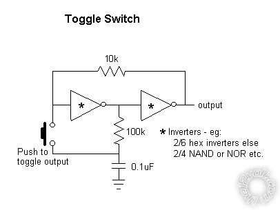
Otherwise the following provides a toggle/latching signal, but you'd probably have to add a transistor etc to handle the relay's coil current....
Posted By: hotwaterwizard
Date Posted: May 13, 2011 at 1:28 AM
Help me understand this better.
The way I took it you actually have two switches.
One to set the lock ( a Pushbutton ) and the Break switch to Unlock.
An Led lights when you push the button and it goes off when you push the break switch with your foot
Am I missing something? ------------- John DeRosa (Hotwaterwizard)
Stockton California
When in doubt, try it out !
Posted By: airticulated
Date Posted: May 13, 2011 at 2:41 AM
You have it correct except i would like to be able to turn it on and off with the momentary button (lighting the led when its on) The brake shuts it off in case I forget to do it manually
Posted By: airticulated
Date Posted: May 14, 2011 at 4:03 AM
Basically one way to turn it on (button) and 2 ways to turn it off. (button or brake)
Posted By: airticulated
Date Posted: May 14, 2011 at 3:40 PM
So what are you thinking? I am hoping to get this wrapped up and installed this weekend.
Posted By: hotwaterwizard
Date Posted: May 16, 2011 at 2:12 AM
Two Push buttons and the break switch would be easier
------------- John DeRosa (Hotwaterwizard)
Stockton California
When in doubt, try it out !
Posted By: airticulated
Date Posted: May 16, 2011 at 2:17 PM
Thanks for the reply hotwater. I will fall back to 2 buttons if i cant make 1 work. Keep in mind the input that the system needs to lock the t/c is a ground not 12v.
Posted By: airticulated
Date Posted: May 16, 2011 at 11:44 PM
Does anyone have a diagram for-
Latched On/Off Output Using a Single Momentary Negative Pulse - Negative Output
Posted By: oldspark
Date Posted: May 17, 2011 at 2:37 AM
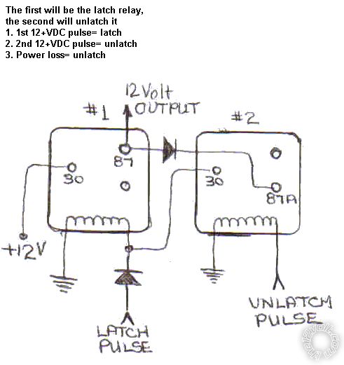
The following are almost equivalent latching relay circuits but for +12V output.
To [i[]invert for a grounded output, a second SPST relay would be added to the output - ie, ouptut to #86; ground to #85 & #30m with #86 being the grounded output when the first relay is latched.
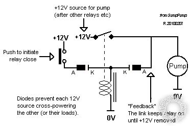
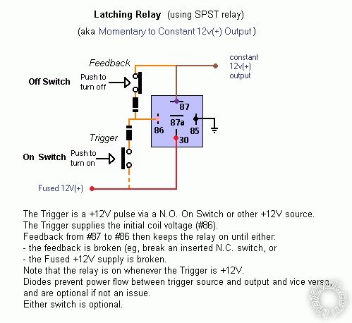
The circuit diagram shows a pump as the output whereas the wiring diagram shows the +12V output with the pump omitted, and includes an optional Normally Closed momentary switch to break the circuit if wanting to do so without removing the main +12V power.
FYI - the two +12V sources in the first circuit diagram can be the same (as indicated by the dashed interconnection in the second wiring diagram). It was drawn as two separate +12V sources to highlight that they could be independent.
And there is still the previous "Toggle Switch" using inverters which could control a relay of either polarity.
It should be easy to add a pulse- or switch-off (from a brake switch) since a hex inverter IC will have 4 unused inverters and quad NOR or NAND ICs will have 2 spare gates, but I haven't worried about that for lack of response.
And yes - the +V and GND power connections to <whatever> gates (inverting, NAND, NOR) are not shown, but they are usually pins #14 and #7 on hex inverters and quad-gate Integrated Circuits.
(We should be using an 8-pin PIC - so much easier circuit-wise!)
Posted By: airticulated
Date Posted: May 17, 2011 at 2:17 PM
Thanks for the replies oldspark. I didnt realize this was going to be as complex as it has turned out. A few of the replies even have verbiage and diagrams I dont fully understand. I am trying to stay away from 2 buttons and latching switches. One button for on and off and a brake switch backup off. I do believe you are right that a PIC is what we need to accomplish exactly what I want. I have never worked with them and have none of the equipment to do so. What would someone charge me to program one and send it to me in a plug and play fashion?
Posted By: oldspark
Date Posted: May 17, 2011 at 5:38 PM
Maybe $20 if it were a school project.
Otherwise I'd assume $hundreds as a contract job.
There are a few cheap PIC circuits or kits at mp3car.com from people that have developed dome light dimming solutions ($20-$40). They could be reprogrammed....
Posted By: airticulated
Date Posted: May 17, 2011 at 8:50 PM
Is there anyone on this forum that has the PIC equipment and could program one for me?
Posted By: KPierson
Date Posted: May 18, 2011 at 2:23 PM
I'm currently working on a pretty important project for a customer that is supposed to be done by Friday (I'm not sure if I'm going to pull it off). Once I get that project done if you are still looking for someone I can do it. I would do it for cost of parts plus shipping - typically around $25. This would include the AVR microcontroller (no PICs, sorry), circuit board, power supply, necesarry current limited I/O, with a detachable Molex wiring harness.
-------------
Kevin Pierson
Posted By: KPierson
Date Posted: May 18, 2011 at 2:26 PM
Here is some info on the last project I did for a member here (with pictures): https://www.the12volt.com/installbay/forum_posts.asp?tid=127151&KW=KPierson ------------- Kevin Pierson
Posted By: oldspark
Date Posted: May 18, 2011 at 5:18 PM
Wow! Excellent - not that I am the OP, I'm just wowing!
IMO AVR is much better than a PIC etc.
FYI - I went the AVR-uPC Audrino route in part because it was cheaper ($35) than other PIC/PICAXE solutions on the market ($70), though also largely due my familiarity with older uPCs (68HC11, 6502, 6511 etc) and thinking that was easier than learning PICs.
But maybe the biggest reason was uPC (AVR etc) can do just about anything whereas PICs are limited to their features and program space (though I may go the 8-pin PIC route for some simple project like this and dome/LED dimmers etc).
AVR - FTW!
And $25!! Wow!!
Posted By: KPierson
Date Posted: May 18, 2011 at 5:27 PM
We use 1000s of 8 pin AVRs - mostly Tiny13s. For more advanced 8 pin stuff we use a Tiny45. Typically the Tiny45 comes in to play when trying to calculate RPM (frequency). It's hard to say if PICs are better then AVRs or vice versa - they are just different (like comparing Ford and Chevy).
$25 covers the hardware parts out of my pocket and I donate my time for assembly and programming to help out the community!
-------------
Kevin Pierson
Posted By: airticulated
Date Posted: May 18, 2011 at 10:31 PM
WOW is right. Thank you so much Kevin! This task done the way I wanted was a bit out of my league it would seem. Let me know when you are finished up with what you got going on and we can go over the details and make sure we are on the same page. This is why forums are so great. This one specifically. And to think I thought it was great just for the diagrams...
Posted By: airticulated
Date Posted: May 25, 2011 at 12:34 AM
I sent you a PM kevin
Posted By: KPierson
Date Posted: May 25, 2011 at 5:40 AM
My other project is starting to wind down - why don't you post up, in detail, exactly how you want the system to work and I can start planning it out in my head.
-------------
Kevin Pierson
|