cooling fan relays /w indicators
Printed From: the12volt.com
Forum Name: Relays
Forum Discription: Relay Diagrams, SPDT Relays, SPST Relays, DPDT Relays, Latching Relays, etc.
URL: https://www.the12volt.com/installbay/forum_posts.asp?tid=128144
Printed Date: May 14, 2026 at 7:35 PM
Topic: cooling fan relays /w indicators
Posted By: studiofire420
Subject: cooling fan relays /w indicators
Date Posted: August 04, 2011 at 11:01 PM
Hey there, Kind of new to this and searched everywhere for help.
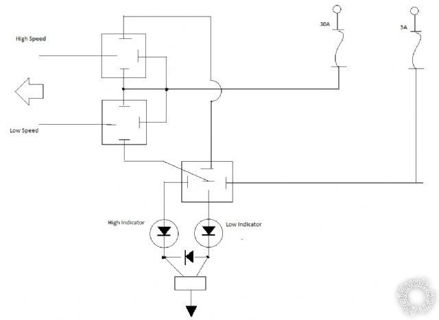
This is the new diagram I made to solve a problem. Aside from diodes across ther 85 & 86 terminals, do I need any resistors for this to work? The high speed setting will light both indicators.
The initial one I wired up burned out the diodes and now every component connected to the same ground is not working. ( the alarm, tach guage, and illumination circuit) This is a kit car and every circuit was hand wired. Everything was working fine untill I added the indicators. I think the relay spiked my electrical system and there are no burnt fuses so I'm really agrivated... Aside from getting this to work I need to cross my fingers and hope that nothing is fried...
Any Ideas??
Replies:
Posted By: howie ll
Date Posted: August 05, 2011 at 4:19 AM
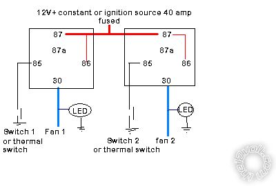
Far simpler than you think, use 12volt LEDs:- DZ3_fans.bmp------------- Amateurs assume, don't test and have problems; pros test first. I am not a free install service.
Read the installation manual, do a search here or online for your vehicle wiring before posting.
Posted By: studiofire420
Date Posted: August 05, 2011 at 4:41 PM
... Yours is so much simpler... Wish I would have done that first. Being as though the entire harness for the car is done.
I only have 2 (-) low current triggers from the switch on the interior. Could I switch your diagram polarity and put the led's on the (-) side of the relay and give them a constant (+)?
My main worry is if I fried something, the mechanic called me this afternoon while him and the body guy were working on it and he tells me that the fuel pump isnt comming on nor is the tach or cluster or wipers and the alarm/locks. I read up on tamping diodes across the 85 and 86 terminals. Direct quote from my electonics book: " Relays powering high current devices such as motors must be protected from premature failure by installing a diode (Commonly reffered to as a tamping diode) in a reverse bias position across the terminals of the coil"..... Does that mean when the original LED's burned out and the fan shut off a high voltage pulse was sent backwards through the ground through all of the devices?? Why wouldn't any of the fuses blow? And do you think all those devices are screwed??
Sorry for all the questions and thanks in advance..
Posted By: howie ll
Date Posted: August 05, 2011 at 4:50 PM
No point, I've already assumed in my diagram that you have a low current switch. Leave the LEDs where they are then you know the relays are working, if you place them where you suggest all you will know is that the switches are working, nothing else.
Diodes aren't needed across the relays in this set-up because all you have "in front" is a simple switch going to ground. Having said that if you must, 1N4004 across 85 and 86 with the bands towards 86.
Please note I also specified a 40 amp fuse or separate 30 amp fuses for each relay. Cooling fans can momentarily draw up to 60 amps each on start-up, i.e. onrush current.
-------------
Amateurs assume, don't test and have problems; pros test first. I am not a free install service.
Read the installation manual, do a search here or online for your vehicle wiring before posting.
Posted By: studiofire420
Date Posted: August 06, 2011 at 12:20 AM
Got it. Didn't think about that. I guess it's better to have the indication from the fan itself. I did add those diodes to the relays as well just for good measure. All is well, thanks.
As far as the electrical system is concerned, I got it all ironed out, one of the fusible links was blown the other had a 8v drop across it. one of the HID assemblies was shorting too, causing a constant battery draw, and the flasher switch was burnt out. Not sure what exactly caused the main problem though as there were pre-existing electrical problems. We had it out for a drive earlier, only thing that still isn't working is the tach... maybe permanent damage from the spike. Probably have the whole car done in about a week now, Interior, alarm and audio system next.
Thanks again!
Posted By: i am an idiot
Date Posted: August 06, 2011 at 8:28 PM
There is nothing in the diagram to switch between high and low speed.
Posted By: howie ll
Date Posted: August 07, 2011 at 1:13 AM
I had separate switching Craig.
-------------
Amateurs assume, don't test and have problems; pros test first. I am not a free install service.
Read the installation manual, do a search here or online for your vehicle wiring before posting.
|