diagram for dual relays for dual fans
Printed From: the12volt.com
Forum Name: Relays
Forum Discription: Relay Diagrams, SPDT Relays, SPST Relays, DPDT Relays, Latching Relays, etc.
URL: https://www.the12volt.com/installbay/forum_posts.asp?tid=128331
Printed Date: May 15, 2026 at 7:50 AM
Topic: diagram for dual relays for dual fans
Posted By: 78mc-bbc
Subject: diagram for dual relays for dual fans
Date Posted: August 23, 2011 at 10:46 AM
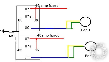
So i am trying to come up with an easy to follow diagram for adding a set of the intrepid fans to a car with a realy for each fan. After researching other's attempts at this online i came up with this below. Can someone more versed in wiring take a look and let me know if this looks like it will work???
PS. i need the two green and yellows going to each fan to operate at high, if you power the green or yellow singularly you only get low speed

Replies:
Posted By: howie ll
Date Posted: August 23, 2011 at 5:14 PM
Are you trying to run both fans at once?
-------------
Amateurs assume, don't test and have problems; pros test first. I am not a free install service.
Read the installation manual, do a search here or online for your vehicle wiring before posting.
Posted By: howie ll
Date Posted: August 23, 2011 at 5:29 PM
Because it looks from that diagram that fan two will only work when fan one's relay isn't powered up. And you haven't shown any differential switching, in other words you will only get one fan at a time. If you want them both to work together, thus:-
cooling_fans.bmp------------- Amateurs assume, don't test and have problems; pros test first. I am not a free install service.
Read the installation manual, do a search here or online for your vehicle wiring before posting.
Posted By: 78mc-bbc
Date Posted: August 23, 2011 at 5:52 PM
yes i am trying to run both fans at once, i dont need the ac activation since the car has no ac. i am trying to split the load from the two fans going on at once to the two relays
Posted By: howie ll
Date Posted: August 23, 2011 at 6:05 PM
If both at once, use my diagram, or better still use a single 80 amp relay with a 60 amp fuse, e.g. Google RAW components, also as a mod, make 86 IGNITION fed, running those two on a constant is going to murder your battery.
-------------
Amateurs assume, don't test and have problems; pros test first. I am not a free install service.
Read the installation manual, do a search here or online for your vehicle wiring before posting.
Posted By: 78mc-bbc
Date Posted: August 23, 2011 at 6:15 PM
so instead of 86 and 87 being tied together, keep 87 going to the battery and 86 to an ignition on location??
oh and thanks for the heads up on RAW they have alot of cool parts
Posted By: howie ll
Date Posted: August 23, 2011 at 6:22 PM
Exactly. By the way, no air? Yuch.
Incidentally I also Googled Nagares but they appear to be a Swiss company.
Radio Spares, AKA RS components in the UK also stock their products. The US equivalents (I believe the same multinational) are Farnell and Mouser.
-------------
Amateurs assume, don't test and have problems; pros test first. I am not a free install service.
Read the installation manual, do a search here or online for your vehicle wiring before posting.
Posted By: howie ll
Date Posted: August 23, 2011 at 6:43 PM
Google Mouser; go to the US version, go to Automotive Relays, from about page 8, 50amps (though 70 is safer).
-------------
Amateurs assume, don't test and have problems; pros test first. I am not a free install service.
Read the installation manual, do a search here or online for your vehicle wiring before posting.
Posted By: 78mc-bbc
Date Posted: August 23, 2011 at 6:51 PM
thanks for the info and help
Posted By: howie ll
Date Posted: August 23, 2011 at 6:53 PM
One more and possibly the best bet for you and a bloody good price, Newark Farnell, part # 30M 9206.
-------------
Amateurs assume, don't test and have problems; pros test first. I am not a free install service.
Read the installation manual, do a search here or online for your vehicle wiring before posting.
Posted By: oldspark
Date Posted: August 23, 2011 at 8:02 PM
With both on, only one relay is required, provided the relay and wiring is of sufficient capacity.
However maybe some redundancy is required, hence 2 relays and wiring paths etc.
In either case, separate fuses also if redundancy is required (or if no spare fuse is carried).
But remember, redundancy may be short lived without some sort of indication, but that can be from noting higher temperatures, or occasional inspection. (That's where a manual-on button or switch is handy.)
PS - Not that I'll mention the HQ of a big monopoly telco whose phone system went down. The back-up batteries were well oversized and there was considerable power and rectifier (charger) redundancy. But the installers did not see the need to extend the alarms (ie, to some monitoring point). Idiots! It worked fine for about 10 years, but then a rectifier fault meant use powering from the battery reserves. 3 days later, their entire HQ telephone system went down. The CEO was not a happy chappy!
Posted By: i am an idiot
Date Posted: August 23, 2011 at 8:42 PM
I really think you need to think about delaying one of the fans. They will pull massive current at startup. It is simple to delay one of the relays so the first fan can start and be leveled out then have the second one start.
If turning them both on at the same time is too demanding on your charging system, let me know.
Posted By: 78mc-bbc
Date Posted: August 23, 2011 at 8:57 PM
how would i wire the second fan to turn on after the first one? wiring is not my strongest subject
Posted By: 78mc-bbc
Date Posted: August 23, 2011 at 9:51 PM
I redesigned it and came up with this, hows this one look. I still need to figure out how to activate one fan then the other

Posted By: oldspark
Date Posted: August 23, 2011 at 10:52 PM
Ah! You need the new UIBI Mk2 - a front end designed to interface to any alternator (including EMS-controlled) so you can add a relay or several relays of your choice (sizing) for use as an (automated) battery isolator.
Not that it's confined to battery isolation. But eventually, it should feature a user-settable time delay. (It's merely a MOSFET buffer that grounds any load - eg, relays.)
The snag - it failed its trial last week - probably because some idiot added "status" LEDs at the last minute. (Damn these Old Farts with their so-called brilliant ideas!) And since then, too many real-life dramas to deal with....
Although delays can be added with a diode and a biggish capacitor (as shown on the12volt somewhere in its Reference Relay diagrams), I prefer to use a smaller cap with resistor and a transistor (or FET) to switch the relay.
But that's a matter for one's DIY expertise etc.
But using your wiring above (which IMO it looks fine), any such delay should be easy to add later. (i am an idiot raised an excellent point!)
And maybe something for consideration, do not discount soft-starting - ie, starting one or both on low speed, and then after a delay, switch to full speed.
Again, quite modifiable in the future, but I mention it in case you are considering cutting & joining the yellow and green wires nearer the fans - away from the relays. (Not that the relays cannot be near the fans - that's usually a space, weather/protection, and access (to repair) issue...)
But don't extend the low-speed wires(s) just for that - unless later access is difficult, or you think it a worthwhile feature.
Besides, some relays can have difficulty terminating 2 wires, though various piggy-back 6.4mm (1/4") spades are available, and there are 5-pin relays with two 87 outputs (occasionally and disastrously confused with the more common 87 & 87a outputs!; not helped by some mislabeling of the extra 87 as 87a - eg Hansa relays).
Incidentally, the beauty of the ground switching to activate the relays is that you simply parallel your desired ground triggers - eg, grounded temp switch, manual on switch, momentary push-button test switch, redundant or emergency temp switch (eg, a $5 Klixon, in case the orig temp switch fails).
Unlike +12V switches, blocking diodes are not required - unless you want one relay's ground not to effect the other.
Sorry - a lot in the above, and harder to explain than show. But that's me!
Posted By: howie ll
Date Posted: August 24, 2011 at 12:03 AM
Peter if you put your glasses on you will see that they are what I call type 87b. Original poster, you've effectively taken my first suggestion and copied it better.
Peter can we have Otter (thermal switches) with different temperature set-ups? That might solve the problem but then I'd run with a pair of 50amp relays not 40s, also why I suggested ignition to 86 not constant.
Craig's point is very valid, especially with the onrush current.
-------------
Amateurs assume, don't test and have problems; pros test first. I am not a free install service.
Read the installation manual, do a search here or online for your vehicle wiring before posting.
Posted By: oldspark
Date Posted: August 24, 2011 at 9:02 AM
The Otters seem similar to Klixons. Often NO & NC versions. Typically spade connectors.
The ones I typically see range from about 50°C to 180°C, sometimes in 10°C increments, others more randomly. And generally 5A switch/contact rating. I use one as my car's electric fan temp sensor.
Thanks for the glasses tip (it was empty!), but it was no mistake. I meant what I wrote, and what I wrote was correct. I know yours are SPDT (type 87a).
I'm talking about SPST with twin output terminals which are correctly labelled 87 & 87. But Hansa labelled them 87 & 87a (I have 2 examples). When 30 toggles between 87 & 87a which are +12V and ground, substituting a Hansa relay with 87 & 87a internally joined together is very colorful!
I used to use the "twin 87 terminal" relays if I had 2 spades to be joined.
Posted By: howie ll
Date Posted: August 24, 2011 at 9:04 AM
I used the 87b for indicator switching (polarity and current) on early Clifford alarms which only had 1 low current neg light/indicator output.
-------------
Amateurs assume, don't test and have problems; pros test first. I am not a free install service.
Read the installation manual, do a search here or online for your vehicle wiring before posting.
|