latched on/off relay not working properly
Printed From: the12volt.com
Forum Name: Relays
Forum Discription: Relay Diagrams, SPDT Relays, SPST Relays, DPDT Relays, Latching Relays, etc.
URL: https://www.the12volt.com/installbay/forum_posts.asp?tid=128480
Printed Date: April 19, 2026 at 5:21 AM
Topic: latched on/off relay not working properly
Posted By: firedemonsic
Subject: latched on/off relay not working properly
Date Posted: September 09, 2011 at 11:18 PM
https://www.the12volt.com/12voltimages/latchonoffsp.gif
Assembled this as the diagram stated to. Verified all wiring then went and installed it in my car to manually toggle the Torque Converter Clutch on and off with a momentary button.
Starts open, and turns on when you push the button. But once it is on it won't turn back off. If you push the button you can hear the relays click each time but it will not toggle off after it has been turned on. What's wrong here?
Replies:
Posted By: the12volt
Date Posted: September 10, 2011 at 2:00 AM
It's likely something simple. Can you post a photo of your wired relays as the diagram shows them? -------------  the12volt Support the12volt.com the12volt Support the12volt.com
Posted By: firedemonsic
Date Posted: September 10, 2011 at 2:58 AM
the12volt wrote:
It's likely something simple. Can you post a photo of your wired relays as the diagram shows them?
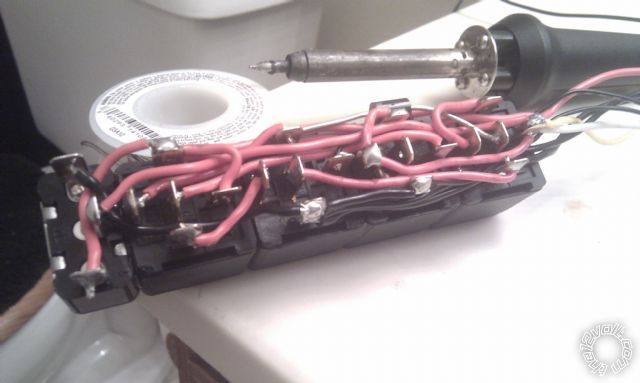
Here is a picture. Relay #1 is on the far right in this photo and relay #4 on the far left. I did make one modification and that was to install a toggle switch to bypass the relays and provide constant 12V if needed however I verified this was not the cause by de-soldering all wires going to the switch and the relay cluster still behaved the same way.
It's going to be pretty difficult if not impossible for you trace the connections since a) I only used red and black wire and b) to keep the footprint as small as possible I did not do any splicing and instead opted to solder all spliced wires directly to their associated contacts IE for the momentary switch, instead of the grounding side being spliced into the ground wire, It's soldered directly to contact 86 of relay #2. I also think this may be the reason It's not functioning correctly. I verified all connections 3 times and although everything checks out maybe the contact soldering instead of wire splicing is creating a short since electricity likes to take the path of least resistance?
Posted By: the12volt
Date Posted: September 10, 2011 at 4:48 AM
Just from a quick peek, it looks like the lead of the diode on 87a of relay #1 is touching 87. That would definitely keep it on. I'll have a harder peek later if that is not the issue. ------------- the12volt Support the12volt.com
Posted By: i am an idiot
Date Posted: September 10, 2011 at 6:44 AM
My new signature may read: R1 riders have vision like Steve Austin.
Posted By: howie ll
Date Posted: September 10, 2011 at 9:33 AM
And the first lesson which you will now always remember is:-
Shrink sleeving on diodes, as in all the P's.
Doesn't matter if you use the same two colours, something I would never do, as long as you know it. Mr. I didn't spot it because he now rides a uni-cycle and his eyes have gone funny.
-------------
Amateurs assume, don't test and have problems; pros test first. I am not a free install service.
Read the installation manual, do a search here or online for your vehicle wiring before posting.
Posted By: firedemonsic
Date Posted: September 10, 2011 at 10:50 AM
The lead is actually not touching. It's just the angle the photo that makes it look that way.
Posted By: the12volt
Date Posted: September 10, 2011 at 10:59 AM
The other thing I noticed is that you do not have a diode across the coil of relay #2. Beyond that, it is difficult to follow each lead in your photo. I know you said you checked the wiring more than once, but I'd go over each connection again and verify each relay is working properly independant of the others. ------------- the12volt Support the12volt.com
Posted By: howie ll
Date Posted: September 10, 2011 at 11:07 AM
If the lead isn't touching but it's close.....
Always think of the worst scenario, especially when exposed to the weather. Mount relays terminals down, this will let gravity help the electromechanical movement AND allow any moisture to escape.
Don't solder, relays might fail.
If anything use a water proof box to IP68 in which to mount the relays.
Thoroughly spray with a moisture retarder as you should do on hood pin switches.
-------------
Amateurs assume, don't test and have problems; pros test first. I am not a free install service.
Read the installation manual, do a search here or online for your vehicle wiring before posting.
Posted By: the12volt
Date Posted: September 10, 2011 at 11:07 AM
i am an idiot wrote:
My new signature may read: R1 riders have vision like Steve Austin.
;-) ------------- the12volt Support the12volt.com
Posted By: howie ll
Date Posted: September 10, 2011 at 6:52 PM
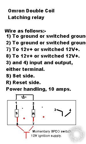
A simple alternative would be to use a twin coil Omron latching relay G6CK-21148-US12DC. Sufficient for 10amps, if more simply add a regular 5 pin SPCO relay*. You would need a SPCO momentary switch to control it.
Look at this:- 96Z_omron_g6ck-_2114p-us12dc.bmp
*Assuming ignition control of the circuit rather than constant ------------- Amateurs assume, don't test and have problems; pros test first. I am not a free install service.
Read the installation manual, do a search here or online for your vehicle wiring before posting.
Posted By: firedemonsic
Date Posted: September 12, 2011 at 1:20 AM
Here we go again. Tore the whole thing apart and re-assembled it. Still doing the same thing.
I color coded the wires and shrink wrapped the diodes this time around to make life easier.
One strange thing I noticed is that once the relays are activated, when measuring the output voltage on #30 of relay 1 there is a slight voltage drop from the input as if it is being passed through a diode. But looking at the diagram, the main flow of current should be independent with the diodes only controlling the coils. If I keep #30 of relay 3 grounded simulating HOLDING the momentary switch, the voltage drop on #30 of relay 1 goes away and I get the same as the input voltage. If I remove the ground of #30 relay 3, the voltage drop returns but the relays still refuse to switch off. What gives?
https://i51.tinypic.com/op6a76.jpg
Posted By: hotwaterwizard
Date Posted: September 13, 2011 at 12:23 AM
Sounds like one or more of the relays are malfunctioning.
I never solder on this type of relay.
The plastic melts inside of the relay and sometimes a connection solder inside of the relay melts too.
Go get new relays and sockets and wire it up with wire nuts and I'll bet the problem goes by-by. ------------- John DeRosa (Hotwaterwizard)
Stockton California
When in doubt, try it out !
Posted By: firedemonsic
Date Posted: September 13, 2011 at 9:41 AM
hotwaterwizard wrote:
Sounds like one or more of the relays are malfunctioning.
I never solder on this type of relay.
The plastic melts inside of the relay and sometimes a connection solder inside of the relay melts too.
Go get new relays and sockets and wire it up with wire nuts and I'll bet the problem goes by-by.
None of the relays are malfunctioning. I tested each one individually when I had it dis-assembled. Each relay tests for continuity between the two 87 contacts, with continuity between the two 87 contacts and 30 when the coil is powered then breaks continuity again when power to the coil is removed. Both diodes test in only one direction.
In fact, looking at this diagram the constant on voltage drop I'm seeing apears to be normal. Here's why:
- Upon initial power and ground relays 1, 2 and 4 are open. Relay 3 is closed via constant coil ground and constant coil power coming from the purple wire which is constantly powered via the 87 contacts of relay 1, so it will never operate in open mode under normal circumstances.
- Upon press of the momentary button, relays 1 and 4 close from the now grounded coils through the gold and dark green wires which get their grounds from the light green wire going to the momentary switch.
- Upon release of the momentary button, relays 1 and 4 now open due to the interrupted ground, however relay 2 remains closed due to the blue output wire being constantly powered from the pink wire which in turn get's It's power from the constantly powered purple wire (Remember the purple wire stays constantly powered from the 87 contacts of relay 1).
- Relay 2 will now never open again until main ground/power is interrupted due to it sustaining It's own coil power from the blue output wire which is being fed by the pink wire. Even when the button is released and power flow from the main red to the main blue wire is interrupted electricity still has an alternate path to take to power the coil of relay 2. This explains the always on voltage drop I mentioned earlier because the voltage being measured is originating from that purple wire which is actually a diode. This also means that while I drove around the block during testing my TCC was being powered through a 3amp diode
After that, the next press of the momentary button closes relays 1 and 4 due the restored ground through the gold and dark green wires, then open again when the button is released due to interrupted ground, and that's all it does with each press from then on.
Unless I interpreted all that wrong, I'm not understanding where the latching on/off part is supposed to come in. Please correct me if I missed/misunderstood something.
Has anyone here actually ever built this before with success?
Posted By: the12volt
Date Posted: September 13, 2011 at 10:05 AM
I just read the first part of your reply. Your relays should be SPDT relays with terminals 30, 85, 86, 87 and 87a. If any of those relays has two 87 terminals, that's the problem. Terminals 87 and 87a should not have continuity. ------------- the12volt Support the12volt.com
Posted By: oldspark
Date Posted: September 14, 2011 at 3:31 AM
It's times like this I prefer my single SPST relay solutions (using a momentary on push-button and an inverter chip, else a momentary on push-button and a momentary off push-button).
Posted By: howie ll
Date Posted: September 14, 2011 at 3:37 AM
The irony here Peter is that this could all be achieved with a momentary SPCO switch and a single dual coil SPCO latching relay.
-------------
Amateurs assume, don't test and have problems; pros test first. I am not a free install service.
Read the installation manual, do a search here or online for your vehicle wiring before posting.
Posted By: oldspark
Date Posted: September 14, 2011 at 7:53 AM
Yeah - but you know me - I like using common components...
|