Im building a projector lift for my movie room and Im having a hard time wiring the actuator for what I want it to do.
I want to be able to push a button ( right now I have a 3 way rocker DPDT) and have the actuator to extend all the way out and stop. Then I want it to push the button the other way and have the actuator subtract all the way and stop.
Now, I have been able to wire up some relays to switch polarity but I have to hold the button down till the actuator moves the whole length.
I've also manage to wire up some relays to constant, to just be able to push the button once and the actuator moves the whole lenght,but I cant seem to figure out how to wire the relays for a constant configuration AND be able to switch polarity.
I 've using the diagrams in these forums, but I cant seem to find one for my application.
Thanks.
Even without a limit switch you could do this with 2 push-button switches and a single DEI 529t assuming the circuit is running on 12 volts. The 529t is reactive load sensitive and also assuming the current draw is within the 7 to 12.5 amp draw of the average window motor.
-------------
Amateurs assume, don't test and have problems; pros test first. I am not a free install service.
Read the installation manual, do a search here or online for your vehicle wiring before posting.
Yes, it does have built in limit switches.
It is a 12v actuator and its rated at 5 amps. I'll try the window roll up module and see how much damage I can do with it!
Thanks.
I thought the poster wanted one-touch.
-------------
Amateurs assume, don't test and have problems; pros test first. I am not a free install service.
Read the installation manual, do a search here or online for your vehicle wiring before posting.
It is one touch. Toggle or rock it up and it extends the actuator. Toggle or rock it the other direction and it retracts the actuator.
Just incase he wanted simplicity and not have to deal with relays and such.
How does that give it one touch? What am I missing Craig? Surely the poster has to hold the switch all the time rather than one touch.
One assumes a DPDT centre off momentary A.K.A. a window switch is already part of the kit.
-------------
Amateurs assume, don't test and have problems; pros test first. I am not a free install service.
Read the installation manual, do a search here or online for your vehicle wiring before posting.
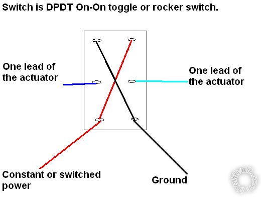
He said the acuator has internal limit switches. The switch in my diagram is an On-On, not momentary nor center off. It will always have 12 volts across the actuator. The limit switches internal of the actuator will break power to the motor when it reaches end of stroke.
I guess the more accurate question would have been does your actuator have adjustable limit switches?
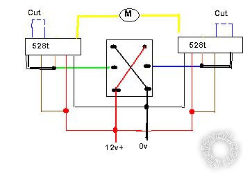
One shot my way:-
one_shot.bmp
You will need 2 x DEI 528t timer relays around $10 or less each.
First time how long it takes for the actuator to work both ways with it's load attached, then add 2 secs. to each direction. (Down might take less than up). Remember these times, e.g. 4 secs.
Bench wire the 528ts. Red to 12v+, black to 0v and BLACK/ white touch to ground. You can see the internal relay actuate. Set the timer pot to the nominal time, e.g. 4 secs.
Now wire exactly as per the diagram, cut the motor wires, green and blue and in each case join the switch side to the orange and BLACK/ white of the 528t.
Join the motor sides to the yellows.
Join the 528t browns to the reds and connect to your 12v+ source.
Joins the 528t blacks to your 0v source.
Cut both blue loops.
That should give you your one touch.
-------------
Amateurs assume, don't test and have problems; pros test first. I am not a free install service.
Read the installation manual, do a search here or online for your vehicle wiring before posting.