using 4v to switch12v ign live
Printed From: the12volt.com
Forum Name: Relays
Forum Discription: Relay Diagrams, SPDT Relays, SPST Relays, DPDT Relays, Latching Relays, etc.
URL: https://www.the12volt.com/installbay/forum_posts.asp?tid=128698
Printed Date: April 18, 2026 at 10:02 PM
Topic: using 4v to switch12v ign live
Posted By: audiman28q
Subject: using 4v to switch12v ign live
Date Posted: October 01, 2011 at 4:26 PM
Hi Guys need to pick your brains.
This is a bit complicated but ill keep it as short as poss.I have a 99 Audi A4 B5 2.8 Quattro that runs the stock Concert head unit no OE disc changer the unit has an interface connected to it that allows the use of an Alpine 6 disc changer accessed via the mode button on the head unit. also connected to this (all of these are on standard ISO connectors) is a Soundlinx MOD01 AUX interface that allows switching between a further two audio inputs connected to one of these via RCA is a Parrot MKi9200 Bluetooth car kit.The Soundlinx provides a push button channel selector & status LED-no LED-changer output,solid LED-car kit/phone output,flashing LED-spare channel output.The problem I have is that when the mode button is pressed and the car kit/phone output (solid LED)is selected the changer continues to run-it doesnt play-no music can be heard but it just plods on through all the discs in the changer until either the mode button is pressed or the ign switched off.What i need you guys help with is coming up with someway of using the Soundlinx power to kill the ign live to the changer when the carkit/phone is selected.The status LED supply is 4 volts and I was wondering if i could use this in someway relay/circuit to switch the changer power off.was thinking of using a relay but i belive their min voltage is 8 volt to trip the coil.any ideas,thoughts or whatever will be greatfully rec.
Yours-Audiman28q
Replies:
Posted By: howie ll
Date Posted: October 01, 2011 at 5:35 PM
Or of course just obtain the radio pin outs and use the Parrot's low level outputs, speaker +, - and mute to input the radio directly.
If you speak to Armour Auto or Parrot's tech boys, there is a plug to fit into the back of the Audi head unit that will do it probably 06-088B
-------------
Amateurs assume, don't test and have problems; pros test first. I am not a free install service.
Read the installation manual, do a search here or online for your vehicle wiring before posting.
Posted By: howie ll
Date Posted: October 01, 2011 at 5:37 PM
Oh and throw away the Soundlinx interface.
-------------
Amateurs assume, don't test and have problems; pros test first. I am not a free install service.
Read the installation manual, do a search here or online for your vehicle wiring before posting.
Posted By: audiman28q
Date Posted: October 01, 2011 at 6:25 PM
thanks for the reply-of course works well if your a pro which it sounds like you are however im not.I can see where youre coming from but cant see how this stops the problem of the changer continuing to run as surely you would still need to use the mode button to select the input from the parrot or am i missing something here.any chance of a little more clarification please-cheers.
Posted By: i am an idiot
Date Posted: October 01, 2011 at 8:19 PM
A transistor and a 5volt relay. I will find a suitable drawing tomorrow.
Posted By: howie ll
Date Posted: October 02, 2011 at 1:28 AM
No it's automatic! Not installed correctly.
Mute signal from the Parrot will switch the head unit inputs automatically. You might even be able to buy that kit from an Audi dealer (at what price?).
Don't go for a clever remedy, keep it simple and make those phone calls tomorrow.
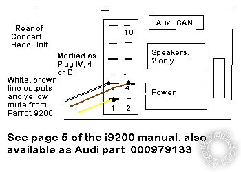
If you look at the rear of the Audi head unit you will either have a row on top of the 2 x ISO plugs, or down the centre. Fully loaded that slot has green, yellow and blue plugs in it. The green is the one, yellow for amp and blue for factory CD changer.
-------------
Amateurs assume, don't test and have problems; pros test first. I am not a free install service.
Read the installation manual, do a search here or online for your vehicle wiring before posting.
Posted By: howie ll
Date Posted: October 02, 2011 at 3:13 AM
This is the correct pin configuration, it will save you from having to push buttons on phone calls. Connecting the mute SHOULD pause the CD transport but I can't guarantee it, we have Grundig (now out of business) connecting to Alpine via a third party (PAC? although Mr. I knows better than me), none of the above parties will help you.
I can't because I have Alpine HU and changer, which DOES pause during phone calls + auto answer on my Parrot (in the settings menu), so nothing is touched!
Yes I'm a pro as is Mr.I, he more on the electronic side, me installation which surely is why you posted here in the first place.
Sorry for sounding patronising but KISS is the first rule:- concert.bmp------------- Amateurs assume, don't test and have problems; pros test first. I am not a free install service.
Read the installation manual, do a search here or online for your vehicle wiring before posting.
Posted By: audiman28q
Date Posted: October 05, 2011 at 12:32 PM
Hi guys sorry for the delay replying to you both work commitments took over unexpectedly.thanks for your replies and your help can see where ur coming from Howie and agree simple is best just that im dealing with an install someone did prior to me getting the car so working with what ive got but ill certainly try it and let u know the outcome and Mr I i would appreciate seeing a diagram of the relay and transistor you mentioned-Thanks again guys.
Posted By: i am an idiot
Date Posted: October 05, 2011 at 12:36 PM
Which voltage changes when the LED illuminates? Does it always have ground and the positive voltage comes in when it lights? Or does it always have +4 and the ground is how they get it to come on?
Posted By: audiman28q
Date Posted: October 05, 2011 at 1:15 PM
Now theres an interesting question-I dont know-know what you mean tho-does the live switch or the +ve,ill have to have a play with the old multimeter and come back to you-cheers.
Posted By: audiman28q
Date Posted: October 06, 2011 at 1:41 PM
Right MrI ive checked out which side switches on the LED-its the 4v positive,the ground remains constant.when the Soundlinx is in the changer position the voltage at the LED drops to .1 of a volt.when in the car kit position it goes to the 4volt mentioned-hope this helps.
Posted By: audiman28q
Date Posted: October 07, 2011 at 4:56 PM
Hi guys,need a diagram for a 5volt relay and transistor set up as mentioned earlier in this thread-can anyone help-cheers
Posted By: i am an idiot
Date Posted: October 07, 2011 at 8:53 PM
Actually you can use a 12 volt relay. LED positive wire to a 1,000 ohm resistor. Other end of that resistor to the base of a TIP3055 transistor. Radio Shack part number 276-2020 collector of the transistor to terminal 85 of the relay. Emitter of the transistor is connected to ground. You must insulate the tab of the transisitor somehow. You should not need a heatsink. But you should monitor it closely at first to see what kind of heat buildup you get.
Left leg of transistor = base. Center leg = collector. right leg = emitter.
apply power to terminal 86 of the relay.
If you already purchased the 5 volt relay wire it up as follows. LED positive to a 100 ohm resistor. Other side of the resistor to the base of the transistor. Collector of the transistor to 12v. Emitter of the transistor to the coil of the 5 volt relay. Ground the other coil connection of the relay.
Posted By: audiman28q
Date Posted: October 08, 2011 at 5:36 PM
Hi Mr i-got the components well sort of-was wondering if I can use a reed relay for this?also with the transistor which way round do u view it for the poles-its flat with a metal backing to 1 side (heat sink?) and finally from what ive been reading on the net will I need a diode in there somewhere to stop the relay coil damaging the transistor.thanks for your help uve been brilliant-sorry for asking more question but I just want to learn.
Posted By: i am an idiot
Date Posted: October 08, 2011 at 9:40 PM
With the lettering of the transistor facing you, and the legs pointing down, the left leg is the base, center leg is the collector, and the right leg is the emitter.
If the transistor was a smaller one, you may need the diode. The transistor you are using is able to handle the relay backlash without any problem.
How much current does your device draw? What is the current capacity of the reed relay?
Posted By: audiman28q
Date Posted: October 09, 2011 at 2:41 PM
Thanks for that-reed relay is rated at 1Amp max,device is pulling 20mA (if ive read my meter right-lol) so should be ok.
Posted By: audiman28q
Date Posted: October 12, 2011 at 7:24 PM
would like to have a recap of the connections please Mr i-there are no numbers on the relay as u mentioned but I do have a schematic of it,so really would just like a list of what connects to where then I get to play with my soldering iron.many thanks again for all your help.
Posted By: i am an idiot
Date Posted: October 12, 2011 at 8:07 PM
Do you have an ohm meter? How many connections are on the relay, 4 or 5?
Posted By: audiman28q
Date Posted: October 14, 2011 at 3:27 PM
Yep have an Ohm meter ( if I can remember how to use it-lol) The relay has 4 connections 3 gouped at one end in a triangle and the 4th at the other,imagine a dot to dot arrow-the two outer poles of the triangle are the coil the point of the triangle and the 4th at the other end are the switch- hope that makes some sense.
Posted By: i am an idiot
Date Posted: October 14, 2011 at 5:38 PM
If the coil is marked, then the other 2 are the contacts of the switch inside the relay.
Posted By: audiman28q
Date Posted: October 15, 2011 at 1:25 AM
Yep thats spot on-well thats how read it-so just need to recap on what connects to where please. Got the +ve from the led to the 100Ohm resistor the other side of that to the base of the transistor,the collector to 12v,the emmiter to the coil of the relay and the other side of the coil to ground-only thing i cant see is what the switch part of the relay has connected to it and where the 12v connection back to the device im switching goes-prob just me being thick-pmsl.thanks.
Posted By: audiman28q
Date Posted: October 20, 2011 at 2:46 PM
hi Mri dont know if your out there or had a chance to read my last post-just a bit stuck at the mo.look forward to hearing from you.
Posted By: howie ll
Date Posted: October 20, 2011 at 4:56 PM
You could have done this job in 5 minutes for less cost if you'd have listened to my post.
-------------
Amateurs assume, don't test and have problems; pros test first. I am not a free install service.
Read the installation manual, do a search here or online for your vehicle wiring before posting.
Posted By: audiman28q
Date Posted: October 21, 2011 at 2:44 PM
yep youre right Howie i could-but then i wouldnt have learned something new and if this doesnt come off then I will use your way but im in no real rush to do it either way-just enjoying the learning experience which is what lifes all about.
Posted By: howie ll
Date Posted: October 21, 2011 at 5:11 PM
Your not wrong if it helps you to learn things, it's just that I have to do a job, efficiently and relatively quickly and most of all one that works first time.
-------------
Amateurs assume, don't test and have problems; pros test first. I am not a free install service.
Read the installation manual, do a search here or online for your vehicle wiring before posting.
Posted By: oldspark
Date Posted: October 21, 2011 at 5:22 PM
You're (Howard) is just happy he didn't do the teaching...
FYI - I tend to avoid the "low volt" actuation issues. I seem to have troubles conveying either get behind the LED or whatever (ie, to the actual "switch") else use a FET or (more likely) a transistor.
Posted By: audiman28q
Date Posted: October 22, 2011 at 3:46 PM
apreciate you have a job to do and the way you have to do it Howie and thank you very much for the time you took to reply and explain,im the same in my job has to be right first time and in the quickest poss way which when youre building race engines doesnt always work-lol.know past the basics with vehicle electrics just want to get toknow more about the electronics side-always eager to learn.As for old spark-thanks for the post-Howies done his teaching in his own way-know what you mean about the low volt switching,I am using a transistor-well iwill be if I can get a little more info,then hopefully it will all work nicely if not Ill fry something (prob me!) and end up using Howies way-pmsl.
|